
graziano-g
Guest
Hi.
I'm sorry if I refer to inventor on time but I know that and sw I'm learning how to use... .
inventor: design a sketch in part environment, I insert it in environment together then select insert frame from the design menu.
now opens an interface in which I can choose besides the profile features also its orientation relative to the path....
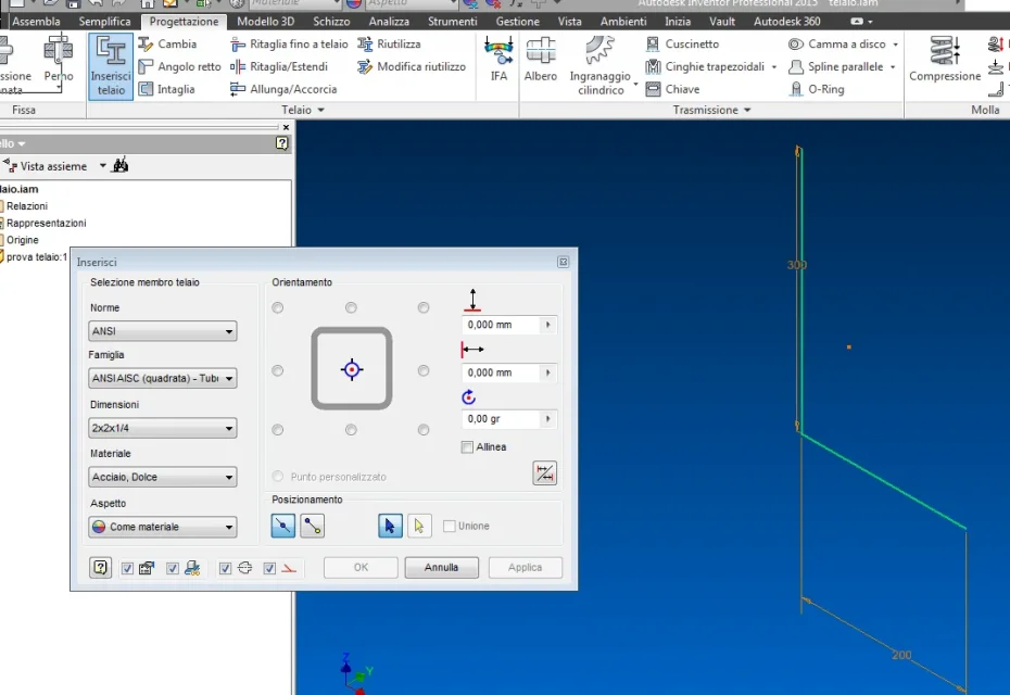 horizontal tubular with central orientation
vertical tubular with orientation according to selected pattern with offset and rotation compared to the vertical line. I think it's better than the procedure you have to do in sw or better than the one I know, but apart from this, what I would like to know is if there is a possibility in sw to decide the orientation of the profile.
Thank you.
I'm sorry if I refer to inventor on time but I know that and sw I'm learning how to use... .
inventor: design a sketch in part environment, I insert it in environment together then select insert frame from the design menu.
now opens an interface in which I can choose besides the profile features also its orientation relative to the path....
horizontal tubular with central orientationvertical tubular with orientation according to selected pattern with offset and rotation compared to the vertical line.
I think it's better than the procedure you have to do in sw or better than the one I know, but apart from this, what I would like to know is if there is a possibility in sw to decide the orientation of the profile.Thank you.