• This forum is the machine-generated translation of www.cad3d.it/forum1 - the Italian design community. Several terms are not translated correctly.

superficial bitch.

  • Thread starter Thread starter solarlord
  • Start date Start date

solarlord

Guest
Hello, everyone.
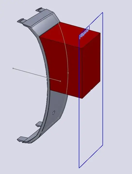
I have a curved surface and I would like, to pertire from it, to get the negative that is a parabolic extrusion that corresponds to the concavity of the surface.
How can I do that?
Hello and thank you
 
You could do a simple extrusion by creating a sketch on a floor at a certain distance from your surface, and realize the extrusion "to the surface".
to completely fill the superfie, the sketch must be made with "convert entities", i.e. open the sketch select all the edges of the surface and project them on the chosen plane.

I use this method to make males in injection molds.

other method is to work in surfaces, i.e. do a 3d sketch by selecting all the edges of your surface and make convert entities, then do a sketch with a line that will be the direction of extrusion, and then do a "extruded surface" that will be the lateral surface of your "mask".
then realize a closing surface of your "guscio" and in the end we get solid with "unisci surfaces".

choose you!:wink:
 
You have to bear some patience.
I come to this point and then I can't move on.
the first version gives me as impossible to achieve.
The second arrival here...
 

Attachments

You have to bear some patience.
I come to this point and then I can't move on.
the first version gives me as impossible to achieve.
The second arrival here...
..caro solarlord:cool:
What do you expect us to understand your file's problems if you place an image?
let us see the native file of swx, so that you can put your hand and find the solution.

Meanwhile so to the eye (maybe mistaken, but what do I know?) that is a set of faces of a solid and not a surface. . But if it were, a surface can be obtained and another solid "negative". but you need to know how that lid is shaped. mail the file! zippers, rarris, make a compressed folder, whatever you want, and attach that.. a pdf does not serve anything (you see at least the tree..), just to engage space in the gallery.

and read some threads back, you just talked about something similar.

greetings
Mar
 
Suppose it's a closed solid.
first you have to close the holes with surfaces/cancel surface, then proceed to create the sketch as mentioned by cat using the outer edge of the surface you want to get, on a floor away from the piece. use offset and do not convert entities (then I explain why...!), giving an internal but zero offset. then do an extrusion "up to the body" by not joining. if it doesn't work, repeat after giving offset to the sketch line internally, before about 1mm to see if that's the problem (the tangences are bad beasts...), then reducing it away, maybe a few thousandths. You'll come to a point that the error will be negligible compared to the size of the piece.

If it doesn't work, do the zero-distance offset (copy) of the internal surfaces, close them ("cuts" the holes), extend them into their external bodes and repeat the procedure, this time with extrudes up to the surface.
 
You have to bear some patience.
I come to this point and then I can't move on.
the first version gives me as impossible to achieve.
The second arrival here...
then, I can understand two things from your pdf:

1. you are starting from the face of a solid, if you want to apply the first method when you do the extrusion you can simply select "up to the body" and do not combine the results, in this way you will have the "male" as a body itself, and wanting you can do "save bodies" and get a part only with this male.

2.to apply the second method, the 3d sketch must be different from the sketch in which you draw the straight!from pdf it seems to me that you are in a unique sketch and logically the extrusion function finds the same sketch both for the direction and the contours!
so if you do two separate sketches see that the extrusion will be done, and also here do not join the results.

the contour of the 3d sketch then is closed well? You didn't convert more entities into the same points and then I see that it doesn't take you all the affected surface, without complicating your life I would proceed with point 1!

I hope I've been clear...:rolleyes:
:wink:
 
ok ok sampon does not have all the twists. Sorry.
cma the piece was imported from step then niete tree.
I tried both cat solutions and couldn't.....
 

Attachments

You mean that?

-executed for convenience only on a region of piece-

*edit: precise that the advices, however valid, of oldwarper, do not serve as the solid does not have particular problems or intruders :d of tangenze
 

Attachments

I solved it with surfaces, making the 0 offset of the surface and filling the holes,
then I modified your 3d sketch by widening the surface,
I did in another sketch a perpendicular line as direction,
I extruded on the surface the 3d with this line,
created a closing face and combined everything.

I have sw2010, I saved it in step if it does not have this version and I put a jpg with the snapshot of the tree that comes out.

:wink:
 

Attachments

in the method used by c3kkos it is important that the sketch to extrude is just a convert entity of the surface of arrival.

you can also do a unique extrusion by doing as sketch the convert entities of the whole face (external stock), and as the arrival surface you must have a sup. all that is the sum of the face of the solid in question (you get it as offset to 0) and the filling surfaces created on the 3 holes.

:wink:
 
No, you guys can't.
and that I tried to extrude to both surfaces. instead I have to make two separate pieces.
to make the single piece I have to apply the method of cat.....that is not very clear to me though. I have sw08 and can't open the file. cmq you see the tree and I will make some evidence.
Thank you very much to all.....you are good.
Hi.
 

Forum statistics

Threads
44,997
Messages
339,767
Members
4
Latest member
ibt

Members online

No members online now.
Back
Top