• This forum is the machine-generated translation of www.cad3d.it/forum1 - the Italian design community. Several terms are not translated correctly.

symbol never catch after a step file

  • Thread starter Thread starter TorMec
  • Start date Start date

TorMec

Guest
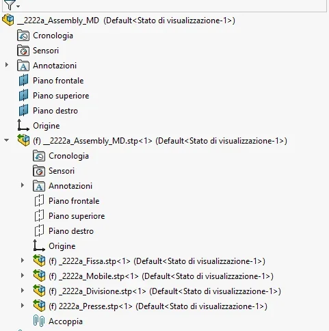
hi to all I opened a step file containing several under assemblies and different parts, none of them sees it as imported and correctly divides the parts from the assemblies but at the time of rescue saved me a unique file excluding all subaxis and all parts. copy the print screen where you notice a green arrow that I have never seen and I suppose is the cause of all this. Can you tell me what that means? I would need to be able to split parts and sub-axes to handle them separately but in this way I can't.
 

Attachments

  • Cattura.webp
    Cattura.webp
    27.4 KB · Views: 83
which is an open file with 3d interconnect enabled.
go to import options and turn it off
 
ah I understood, I opened it on the office jolly laptop that probably activated that option, on my personal pc is not there. question, but disable this option also speed import or not?
thanks in advance
 
I attack the speech by asking you the following question: I downloaded the step of a knit tire cylinder + stem and ,col drag and drop, put it directly in my project. But why don't you do me with the "couple" command move the stem over the shirt?
the 3d interconnect I have already disabled it but nothing
Thank you.
 
need more information.
environment, i.e. part or together, where you are working
environment, i.e. part or together, where the cylinder was created
what are your use capabilities of solidworks
Maybe attach a screenshot to understand the context of what you are doing
 
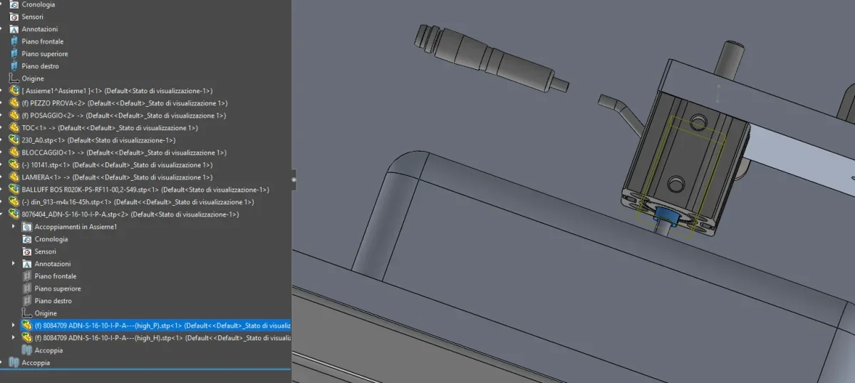
attached I put the screen.. on the right there is the 3d drawing and on the left the tree; the total cylinder code is 8076404 which consists of two components the mesh and the stem (I highlighted it in blue).
cylinder is a step I downloaded from the supplier's website. . I think that's why it doesn't make me ties
How can I do that?
Thank you.
 

Attachments

  • Cattura2.webp
    Cattura2.webp
    49.5 KB · Views: 43
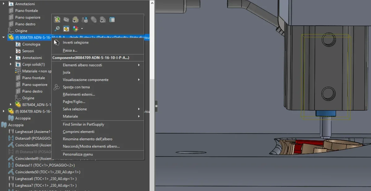
the symbol (f) means that the component is fixed compared to the axieme that contains it, in your case the cylinder. so you have to edit the axieme and with the dx text make the component mobile.
 
first of all thanks to the answer
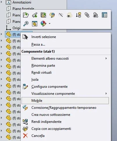
You mean there's a command called "mobile" or something?
no because there isn't..in attachment I put you a screen.. What is the command?
Thank you.
 

Attachments

  • Cattura3.webp
    Cattura3.webp
    48.9 KB · Views: 36
I've always seen you in my context menu since I use sw.
the context menu will activate you if you are an axieme change mode.Cattura.JPG
 
I have already seen both that video and the guide and I have not been useful, otherwise I did not ask you
in the screen I put on it you clearly see that it does not give me the option "fix" or "mobile"
That's the problem. .
 
I have already seen both that video and the guide and I have not been useful, otherwise I did not ask you
first of all you have seen the video and the guide you have not told it and I do not have the power of divination and understand what can be useful to you and what not.
then I asked you what your skills are in the use of solidworks and as you did not respond I assume that they are enough to dexter in the basic settings.
 
I attack the speech by asking you the following question: I downloaded the step of a knit tire cylinder + stem and ,col drag and drop, put it directly in my project. But why don't you do me with the "couple" command move the stem over the shirt?
the 3d interconnect I have already disabled it but nothing
Thank you.
I imagine you want, in the general axieme, to see the various positions of the cylinder...then maximum and minimal stroke. I do it quite habitually.

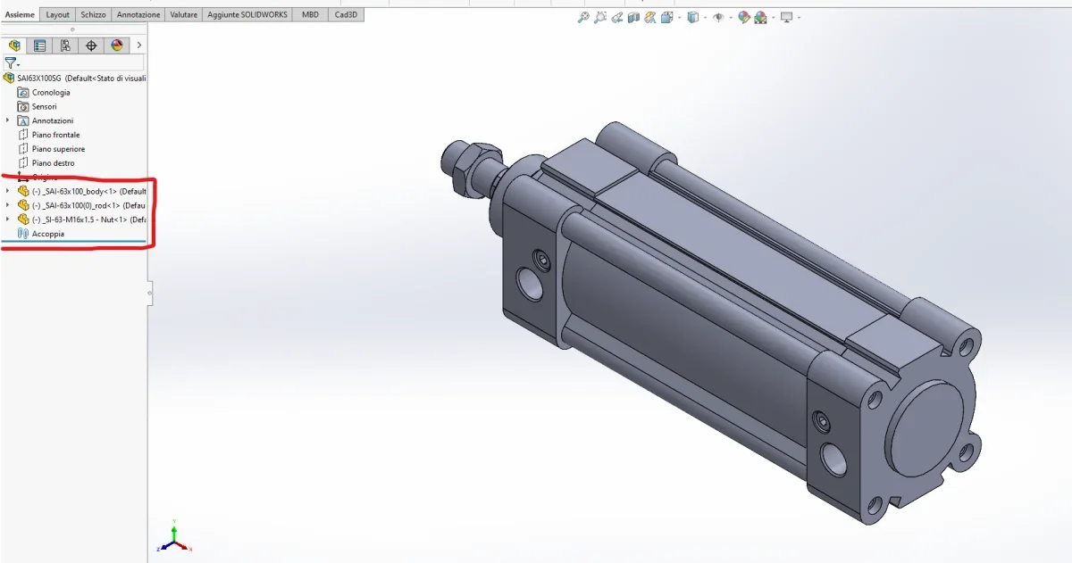
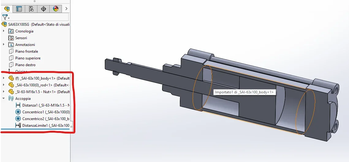
instead of drag&drop directly from the step you downloaded into your set, import the step into a new file, making sure that the 3d interconnect is disabled. as you see in the image in example, there are 3 parts of which no fixed. Esempio1.webpI arrange to fix the first, the body of the cylinder, then I provide to give the constraints. use limit distance to have a cylinder that can simulate the whole race, but normally use 3 configurations or "free run" with the limit distance bond as you see, "max run" going to disable this coupling and create another one that simulses the total output of the stem and "minimum run"Esempio 2.webponce you do this, save the cylinder as a whole and insert it as a subaxieme.
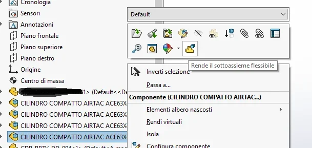
at this point, to simulate the various positions of the cylinder you just need to make the sub-assembly, going right-click, you will see this icon Esempio3.webpIn this way you can freely move the cylinder stem from the mesh.
 

Forum statistics

Threads
44,997
Messages
339,767
Members
4
Latest member
ibt

Members online

No members online now.
Back
Top