• This forum is the machine-generated translation of www.cad3d.it/forum1 - the Italian design community. Several terms are not translated correctly.

thickness and materials for flag clamp base

  • Thread starter Thread starter Jimmy_83
  • Start date Start date

Jimmy_83

Guest
Hello, everyone. I press that I am an amateur in design but I have good manual skills on the ''field'' .
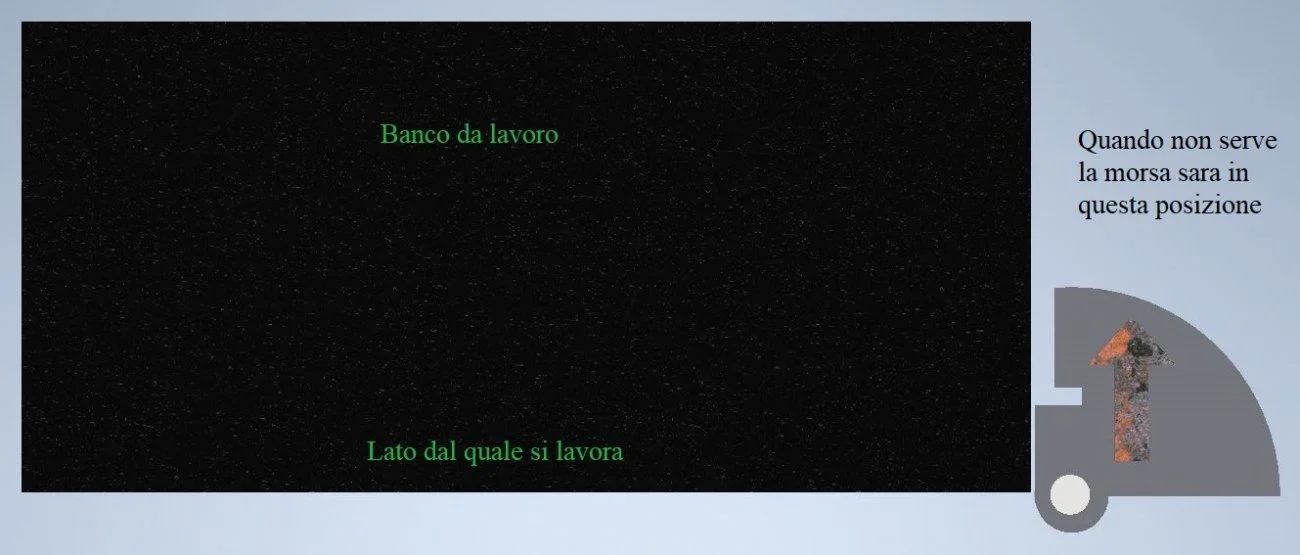
I'd like to put a bite on the flag. In this way the bite is not in the way when not used. the materials I would take them from the carpenter so I do not know the characteristics. as support I thought of a pipe with large thickness or a 55mm diameter round. the 1000mm long tube/tondino will be resting on a roller bearing side floor and near the highest point will have another bearing so that it can turn on the vertical axis easily. the plate on which the clamp will be mounted will be 15mm thick. on the lower face of the plate I will perpendicularly psalm of the rectangle triangles isoscele thickness 5mm and with 250mm cats to give resistance. I wanted to know if someone kindly makes me a simulation or just observations on the sizing. The maximum twist I would like to apply to the clamp is 700nm on the horizontal axis. sorry for the arrow but indicates the orientation of the bite. in front of the arrow you will find the person uses the bite.
thank you so much to anyone who will want to contribute and good Easter to all.
 

Attachments

  • morsa a bandiera.webp
    morsa a bandiera.webp
    24.5 KB · Views: 27
  • base morsa dis..webp
    base morsa dis..webp
    17.9 KB · Views: 34
by tondino you mean a 55 mm full round torsion? where the torque moment enters and where does it go? it is not clear that work must do this application
 
from what you understand the clamp will be fixed (as?) on the plate that, solidarity with the tree, will rotate to be used or put in a situation of encumbrance nothing.
What you need to know is:
the position of the clamp and force implemented on the same.
points of ink of the shaft or where the bearings are placed and their fixing.
also secondaryly:
rotation lock system.
 
Maybe it's just to put it in the counter? :unsures: then is it rotated once a day?
If so.. bearings look like an irrelevant refinement.
rather it is interesting to know that work is carried out on that bite.
If you have to hammer, the springing effect has its importance.
 
Hello and thank you for your interest. I try to answer in order.bizYes, the tondino or tube will be 55mm but if necessary I can increase the diameter. I attach a photo, x indicates the center of the point where the torque moment will be applied. I attach two more photos showing the ''open' bite' is ''closed'. all will serve to have the free completion desk when the bite does not need. when the bite serves instead you have a beautiful big bite. mammalsclamp, support plate and vertical tondino will be supported by welding and bolts. the bearings will be two, one fixing the round side floor, and the other to 30-50mm from the lower face of the plate where the clamp is mounted. the 1000mm long round table will then have a bearing at the base and one at about 950mm. The embossed arrow with ''arrugginita' surface indicates where you are when using the clamp. the three black circles with a lot of approximation indicate the holes to fix the clamp to the base plate. as a maximum force I hypoticcato a 1 meter long lever to which I hang myself 74kg.

for the rotation lock in working position they use a bolt m12 at the point indicated by the black arrow.
Vittorio'' irrelevant refinement '' I don't know if you mean it's a value or a defect but having the chance I prefer to do so. There are no special processes... you do the usual works from ''mechanical Sunday'' during the time I steal from the family. once a day is really exaggerated I will use it once a week. I am of ''83 and therefore hope to use it for the next 20-30 years. with a paint comes really a beautiful artwork also to see. the counter is made of 4mm 1500x700mm stainless steel.
 

Attachments

  • banco _lavoro_chiuso.webp
    banco _lavoro_chiuso.webp
    57.5 KB · Views: 26
  • banco _lavoro_aperto.webp
    banco _lavoro_aperto.webp
    43.2 KB · Views: 26
  • tor. morsa.webp
    tor. morsa.webp
    19.5 KB · Views: 26
Bye-bye jimmy83
I meant that the bearing was not necessary for a jumping rotation.
I, where possible, are for the philosophy of "tool" rather than that of "add".
less things are there.. less things break.
the idea to recover space is great and the doubt that left me the stability of the rotating table during the workings on the clamp, you removed it by inserting the image where you specify the temporary fixing.
 
ok we hope are enough the info I have provided to know the robustness that will have this swivel support. Alternatively, I could complete this and if it were weak to strengthen it later. I have no idea how much effort it takes to make a simulation but I would be fine even if someone who has experience in this area gave me an opinion.
 
As for the plate you should weld ribs, of the handkerchiefs in short, as for the round you will have an estimated maximum arrow of about 3/3,5 mm if the pad at the top is adjustable (which would do to your case) by hinge. I think you have understood that for what you have to do it is more than good.
 
the arrow is difficult to assess if you do not know the constraints and dimensions of the handkerchiefs that you will apply, which in turn affect the force to be applied to the rod for the calculation of the arrow given from the bending moment.I have been conservative, maybe it is even less.
 
biz I'm sorry about the frankness. but if I give you a faithful 3d design in all details you can do this simulation?
 
What's bothering you? tensions due at the moment are not particularly relevant.perhaps the maximum shift, but in this case I think you are not interested or wrong? Anyway, if you want, I'll do it as soon as I have time.
 
I am not worried about the shift due to the bending provided that this falls within the limits and is reversible. in the sense that at rest everything returns to the point of departure. It would be enough for me to know at large if this twisting moment represents 10, 50 or 90% of the ceiling.
Last week I actually adjusted a cart using 400x200x15 plates and seemed appropriate for my project. I'm still waiting for the result of your simulation.
 
you have no need for any simulation. As for the tondo from ø55, this will undergo a sigma stress of about 40 mpa, so considering the yielding load of a s235jr steel, the more "scading" that you can use, you have a safety coefficient of about 5.875 m as for the plate you have a maximum stress
 
If the 15mm floor will not be subject to heavy bumps you don't have to worry much, in case you fail 20mm, always with ribs, and go quietly.
 

Forum statistics

Threads
44,997
Messages
339,767
Members
4
Latest member
ibt

Members online

No members online now.
Back
Top