
• This forum is the machine-generated translation of www.cad3d.it/forum1 - the Italian design community. Several terms are not translated correctly.

toothed wheel

  • Thread starter Thread starter beppe_g
  • Start date Start date

beppe_g

Guest
Bye to all,
I am new to the forum... My name is Giuseppe, I am 24 years old and I am 5th year of mechanical engineering. . .
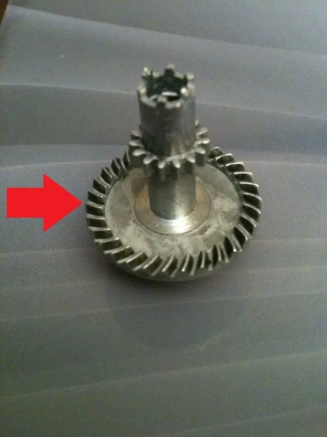
I'm playing on solidworks a fishing reel... for now it's all smooth yarn, but now it turns out to me the problem of playing a toothed wheel "pin"... this kind of gear I never drew it and I wanted to know if any of you are aware of some tutorials or if you can give me some tips.. .
Thank you so much! I'll attach the photo to make you an idea! !
 

Attachments

  • foto.webp
    foto.webp
    136.8 KB · Views: 23
I have the problem of reproducing a toothed wheel "pin"... this kind of gear I never drew it and I wanted to know if any of you are aware of some tutorials or if you can give me some tips.. .
I don't know what kind of trend has the tooth profile, but if it is a constant section you can sweep with the tooth profile as a section and its pattern on the wheel plane as a path. if it is variable section, make a loft between two sections. then make a circular repetition to complete the toothed wheel. of course you have to position and dimensional the reference geometry (planes, guide curves, sections etc.) so that the circular series is consistent with the step/dimensions that must have the teeth without creating overlaps.
I understand that said so may seem excessively easy, but I think that having the geometric information of the tooth is quite trivial to make one and repeat it n times.
 
Thanks marcof...
I tried your way... but I miss the data regarding "heliocydal"... I designed the two profiles, but then I missed the driving curve for the sweep... So now I've drawn the gear with which it's fitting the wheel... I designed the guide spiral starting from the data I measured. . .
How can I project the tooth to plan so that the coupling is perfect?? I don't know if I explain. .

I attach the file of the gear with which it mates... is a .rar with inside the solidworks project
 

Attachments

Thanks marcof...
I tried your way... but I miss the data regarding "heliocydal"... I designed the two profiles, but then I missed the driving curve for the sweep... So now I've drawn the gear with which it's fitting the wheel... I designed the guide spiral starting from the data I measured. . .
How can I project the tooth to plan so that the coupling is perfect?? I don't know if I explain. .

I attach the file of the gear with which it mates... is a .rar with inside the solidworks project
I didn't understand much of what you mean, but look at the section on mechanical couplings... I tell you that solidworks does not mate according to the tooth but according to the ratio (between two gears).
here is the solidworks guide.http://help.solidworks.com/2012/ita....html?id=e3829784c8614134b45803cd30fbfd78#pg0
 
thanks ivan, my problem is to create the toothed wheel that is in the photo and that must mate with what I designed... both in solid and in reality.... in fact I will have to create a working prototype. . .
 

Forum statistics

Threads
44,997
Messages
339,767
Members
4
Latest member
ibt

Members online

No members online now.
Back
Top