CapMec
Guest
Hello everyone, I'm an engineering student and I'd have the following problem to propose. I am redesigning a tool changer and at the point of work to which I arrived, I now have to redesign some thorns that allow the centering between the tool changer and the tool that then the robot will move. However, both because I probably carry some gaps, both because the cad file from which I leave is one of those that download from the sites of the companies, and that therefore it is not detailed, I can not understand how to redesign the plug. first I would have a theoretical doubt: What difference is there, in terms of use, between a cylindrical plug and one instead with internal thread hole? Does the inner thread hole only serve for the extraction of the plug or allows other features? 2 images of the plugs (uni 6364) with/without inner threaded hole.
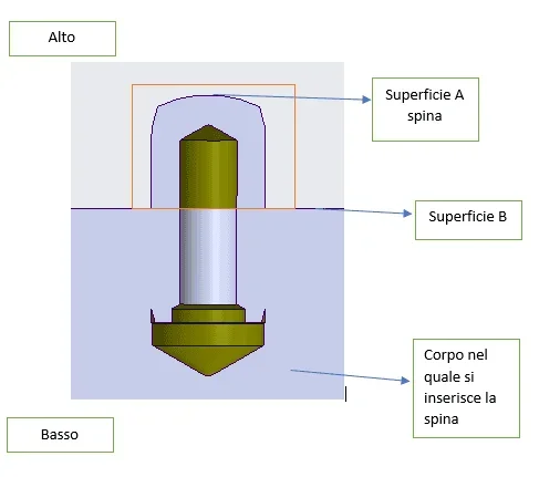
not having therefore understood how to use a perforated plug internally, I can not then interpret the cad from which I leave for redesign. i.e., if the inner thread hole only serves for the extraction of the plug (it is my guess that could be wrong) how would you pull the plug if the hole in which it fits is blind? I attach below 2 more images where I isolated from the model cad the plug and the body part with which it mates (from the last image it seems that the plug has been represented cut and only rested on the upper surface)
I hope I have expressed myself quite clearly and I thank in advance anyone who can answer me.