• This forum is the machine-generated translation of www.cad3d.it/forum1 - the Italian design community. Several terms are not translated correctly.

uso di simulation

  • Thread starter Thread starter Tantocattivo
  • Start date Start date
Yes, I'm sure I got it wrong.
but it seemed to me that you had meant that the load was applied "on the tip" to the rods (key, on the flat face) in axial direction and that therefore all the complex was prompted to pure traction (with the variables of the case in the junction zone between the bolted plates); as I show you in the image (the axial red force I mean):View attachment 14475 (Perdona but I have not yet active swx 2010 and I only see your image)

and from what I hear it seems to me that we all understood that (?).
If so, it is clear that force is applied <on the floor (not plate) which is at the end of the tubular> but the reactions will be found in the boards bolted from the "small" area of union with the bar.

then I was doubtful that the 300kg insisted on the other horizontal "plant" in normal direction, the blue arrow I put. in this case the speech changes, there is no more traction but bending (with "diramations" various always between the boards bolted).. but this only you can tell us by explaining a little better: red arrow or blue arrow?? (or what else did you assume? )

Unfortunately (or fortunately?:biggrin:) if you do not have a minimum of knowledge/experience in order to make these checks "hand" (but also to eye) any fem helps little (in fact, it can do harm). the parameters you have to enter into the program, points of application/reaction of forces etc., consider shape variables, security factors etc. etc. all flour of your sack; If you don't know where to put your hand, stay still at the blocks (or worse you mess up).
the program simply "follows your orders" (we say that it does the accounts for you and displays the results).

greetings
Mar
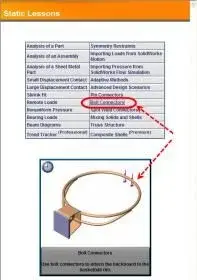
then, I actually had to explain better:redface: and post an image like you did, the 300 kg. are applied in the plane indicated by the blue arrow.
If as you are telling me (and others), that is, you need to know how to do it by hand, then I don't even try. I was engulfed by the fact that seeing What happens to a frame if I put tot kg here and tot kg is quite easy, then I said you want to see that "verify" also bolts is a simple thing, but obviously I was wrong:biggrin: But for now, I'm taking a break, as soon as an engineer arrives, I'm going to explain to me how he does it and maybe we'll talk about it here. thanks to all for the interest.
 
just uniformly I wouldn't say since the load is applied at the end of the bar which has much less section than the surface of the plate. will be more concentrated in the center plate where the bar starts.. unless you consider the complex bar/plate a whole "infinitely rigid", untrue to me.


right,
I would proceed so, "by degrees."
once checked bolts (and quiet that 4 m12 the truck also hold it with the trailer:biggrin:, as they say All i capi..) I would pass to the plate, thickness and extension in relation to the fixing points (always regarding my previous consideration),
Sorry to put me in a question.. .
according to you what is the most correct method to evaluate the complex bar/plate? what verification should be made for the thickness to be able to define the rigid plate and therefore not subject to local deformations that charge the bolts with parasite moments?
the norm (Eurocode) deals in detail with beams at i and h, but it does not seem to me to deepen in detail flanged joints with different forms.
 
what verification should be made for the thickness to be able to define the rigid plate and therefore not subject to local deformations that charge the bolts with parasite moments?
Hello Michael81,
I also read the ntc 2008, but in addition to traction, re-cropping, punching etc of the dishes is not specified any more.
 
Let me disagree. I can't do hand calculations, I'm not a simulation expert with solidworks, I did a basic course but I never used it. but if a "normal" user cannot use one of the wizards that paid thousands of € to validate a simple stuff like this... It's money thrown and shitty palates in the face of retailers. we are talking about 4 screws m12 on a plate. 6 couplings a bond, a force and two welding. at the official presentation of swx 2008 they showed us the validation of a metal goat of a shed. Even putting high safety coefficients seems strange to me that no one unbalances to give a soothing hand. or does the swx fem not use it?
 
or does the swx fem not use it?
I normally use nastran, however when I have to analyze some simple metal piece sw. regarding the proposed piece, I agree that although it seems a simple thing, modeling it in reality is not.
the piece consists of two parts, which are held together thanks to the pretension given by the four bolts. for precision, the cutting load is transferred between one plate and the other by friction that is generated due to pretension. the bending moment is instead transferred in the form of couple to the upper bolts that go in traction, and to the contact between the plates in an imprecisate point of the lower zone that are precisely in compression.
in order to analyze this 'simple component' it is necessary to model the two plates separately considering the contact and friction between them. give the correct pretension to bolts and then solve everything.
As I normally predicted this type of analysis I do with nastran, so I should lose some time to do it with solidworks, but I think it is not exactly a trivial example from which to begin, because of the presence of friction, contact and pretension.
all this is much easier to do by hand rather than to simulate correctly with a software (any it is) and not putting the right settings the result you get is far more approximate than what you can get by doing the accounts by hand.
for this no one makes a fem of such a particular and everyone simply responds that you have to calculate it with the calculator (excel).
 
Let me disagree. I can't do hand calculations, I'm not a simulation expert with solidworks, I did a basic course but I never used it. but if a "normal" user cannot use one of the wizards that paid thousands of € to validate a simple stuff like this... It's money thrown and shitty palates in the face of retailers. we are talking about 4 screws m12 on a plate. 6 couplings a bond, a force and two welding. at the official presentation of swx 2008 they showed us the validation of a metal goat of a shed. Even putting high safety coefficients seems strange to me that no one unbalances to give a soothing hand. or does the swx fem not use it?
the sw fem that was then called cosmos is present only in the full version of the software, which costs a few thousand euros more than the normal one, so if you decide to invest that money you have to also consider investing a little in a course.
verification of a bolted connection may not be a trivial thing (exist entire books on the subject) if you enter the detail; the verification however can be simplified a lot, schematize to the maximum the stresses to calculate the stresses on the bolts (the norm can help...see cnr 10010). I think there's a post with a similar topic in the mechanical design section.
 
just uniformly I wouldn't say since the load is applied at the end of the bar which has much less section than the surface of the plate. will be more concentrated in the center plate where the bar starts.. unless you consider the complex bar/plate a whole "infinitely rigid", untrue to me.
for example a first calculation could start from considering the plate and the beam welded as a rigid set. at least it is easier to verify bolts. see pdf in attachment p 11-14. It can be a start.
more simply without calculating the neutral axis you could take the lower edge of the flange as a neutral axis, cast the distance and its normal load on the bolts. . .
 

Attachments

the sw fem that was then called cosmos is present only in the full version of the software, which costs a few thousand euros more than the normal one, so if you decide to invest that money you have to also consider investing a little in a course.
verification of a bolted connection may not be a trivial thing (exist entire books on the subject) if you enter the detail; the verification however can be simplified a lot, schematize to the maximum the stresses to calculate the stresses on the bolts (the norm can help...see cnr 10010). I think there's a post with a similar topic in the mechanical design section.
my intention with this post was to know if a neophyte, using solidworks simulation, could learn "easy" to make a check on bolts "in general". by verification I mean a rough patch to the problem, a non-university or book calculation as you wrote, not from research study. The example I have put is an example, I know that 4 m12 is a great deal, but precisely I wanted to know how much? 300 kg, do we all know 500? I don't know, 1000 no. It is not that I have to present the calculations to the civil genius, just not to use experience and an eyemeter.

Hi.
 
So, I actually had to explain myself better and post an image like you did, the 300 kg. are applied in the plane indicated by the blue arrow.
If as you are telling me (and others), that is, you need to know how to do it by hand, then I don't even try. I was engulfed by the fact that seeing What happens to a frame if I put tot kg here and tot kg is quite easy, then I said you want to see that "verify" also bolts is a simple thing, but obviously I was wrong:biggrin: But for now, I'm taking a break, as soon as an engineer arrives, I'm going to explain to me how he does it and maybe we'll talk about it here. thanks to all for the interest.
my intention with this post was to know if a neophyte, using solidworks simulation, could learn "easy" to make a check on bolts "in general". by verification I mean a rough patch to the problem, a non-university or book calculation as you wrote, not from research study. The example I have put is an example, I know that 4 m12 is a great deal, but precisely I wanted to know how much? 300 kg, do we all know 500? I don't know, 1000 no. It is not that I have to present the calculations to the civil genius, just not to use experience and an eyemeter.

Hi.
See,
the fact is that everything can be done and everyone can do it.
knowing how to calculate "hand" is not an obligation also because maybe after years of disuse (depending on the activities undertaken) it is lawful not to remember all the formulas, but for this you can brush texts and manuals, consult the norms and what else to get to the result.
However, at least the basic mechanical knowledge must have it (this also applies to users who buy shout softwares by spending thousands of euros thinking that they do everything to them because they saw it at the presentation). a manual must be consulted and the formulas know how to apply them. to know what they are and how they interact the various parameters, and this does not necessarily mean knowing it by menadite memory, but at least to have clearly what you are talking about.

and forgive me,
but when a designer begins to talk about axial load and bolts solicited axially to traction (which could be all summed up "simple" and this you had given us to understand) and then the thing turns out to be all other with normal load and consequent bending I the "physical simulation" would use it to physically detach the power of the pc :biggrin:. .

and this is the demonstration of what everyone is saying to you; simply have idea of what you are doing and at least distinguish and know how to examine the various stresses, then certain that the softwares help and not little.

greetings
Marco:smile::smile:
 
my intention with this post was to know if a neophyte, using solidworks simulation, could learn "easy" to make a check on bolts "in general".
It's a little difficult to answer that question. .
in general the solidworks fem is "simple" if you know how to use it.
However, if you want a board try to do a series of test cases, to verify the reliability of the simulation.
Repeat, make a connection simulation (only subject to axial force), describe the settings used to model the bolts, and post the results, otherwise what we should tell you!

Hi.
 
my intention with this post was to know if a neophyte, using solidworks simulation, could learn "easy" to make a check on bolts "in general".
then if by neophyte you mean a mechanical designer with experience that looks for the first time in the world of the "digital" fem the answer is yes (with limits but beyond); a hairdresser for lady definitely not!:biggrin:

And this is the juice.

greetings
Marco:smile:
 
I understand, I don't do anything for now :frown: . I expect an ing (or who knows how to do it) in the company and then I try to do it in solidworks. I honestly don't know what you mean by a mechanical designer, in the sense of a degree or specific study title there is no I. I am a gemetra who has always designed everything and more, in fury to draw things learning, at school I never made metal carpentry, then working instead on it I learned what are cyanphrines, mating tolerances, machine for processing (fresh, lathe, bending machine etc.). I studied beams, pillars, floors, so I have idea of vectors, moments. I did some tests with solidworks, I had done simple pieces for work and then I tried to put loads on him and see what happened, I managed to see the deformations under load in a dozen steps. then in the company was presented the opportunity to verify some bolts, because some said they were keeping others not, then I said: now I do it in solidworks, but obviously it is not what I can do now.
However a true thanks to all those who have "lost" their time with me in this discussion.
 
more than the diameter of the screw, you should focus on the type of material with which they are made. however better to start from 8.8 (which indicates the beginning of ribbing and other structural parameters of the screw itself). telegraphically 8.8 indicates about 80 kg /mm2. So if you think about m12 (diameter 12) you do the calculation.
 
Bye to all,

in order to face the resolution of your problem, I recommend you to perform the tutorial on bolted connections (as from image), present in swx simulation exercises, which will guide you step by step in setting the "bullone" connectors by solving a similar preble to yours.
Moreover, I recommend you read the attached document describing and showing the use of "bully" connections in swx simulation environment.

Finally, if you place the model in neutral format (parasolid) I see to correctly set the boundary conditions, loads and connections for solving the problem.....before an image showing the conditions.


swarzy.
 

Attachments

Forum statistics

Threads
44,997
Messages
339,767
Members
4
Latest member
ibt

Members online

No members online now.
Back
Top