kubbah
Guest
view not wireframe but see some lines
I don't understand
if I put the shaded view with the edges
but also "hidden lines"
lines are displayed just behind the wall
(I'm sure the paviemtno lines are backwards than the wall)
yesterday I worked on it and it was fine, today I reopened the file and it seems almost a wireframe effect but you only see the lines immediately behind the walls
Any suggestions?
Thank you.
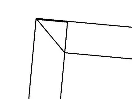
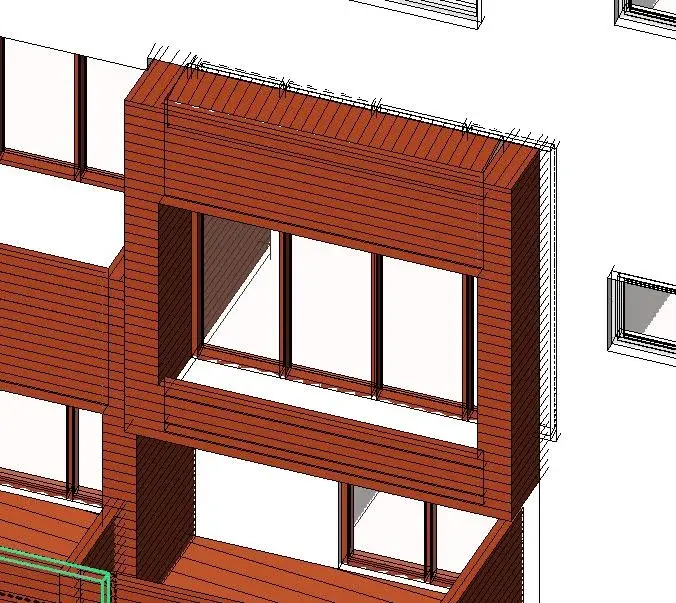
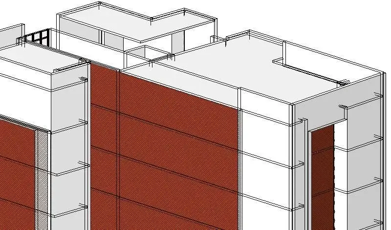


")