• This forum is the machine-generated translation of www.cad3d.it/forum1 - the Italian design community. Several terms are not translated correctly.

welded tubular edges

  • Thread starter Thread starter tanticapelli
  • Start date Start date

tanticapelli

Guest
Hello everyone

I have already found requests for the smoothing of the solid edges but I couldn't find the answer to my specific case.
allego 2 screenshot: the first frames a tubular in welded fe to which I gave 2 mm welding game using the appropriate function within the function "structural element".

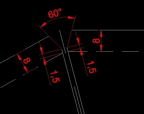
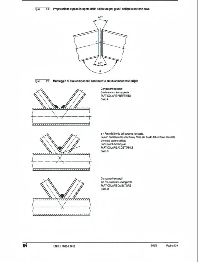
to the same joint though I should try to apply a preparation to the welding as from second screenshot that is taken essentially from the appendix and figure e.6 of the en1090-2:2018 (I attach third screenshot).

Is there a function that "velociously" applies a 60° biellature without going to the bottom edge of the thickness but leaving 1 mm / 1.5 mm intact?

thanks to all
 

Attachments

  • Tubolare con gioco 2 mm.webp
    Tubolare con gioco 2 mm.webp
    13 KB · Views: 17
  • Schema cianfrinatura.webp
    Schema cianfrinatura.webp
    12.6 KB · Views: 18
  • Estratto EN1090-2_2018.webp
    Estratto EN1090-2_2018.webp
    56.8 KB · Views: 17
Isn't the classic bevel good?
It would be good if not, at least as I understood it, you have to do it first on the edge of the sx moncone then on that of the dx moncone and also I did not manage to find a useful angular value to impose (except one but very uncomfortable if put in relation to the scheme I attached) and a pile of distances.
to succeed in getting the result I try to go for attempts by setting up many functions (considering the n of tubes that I have to produce. . . )
 
when ordering structures that require certification en 1090, I place it in order phase and on the drawings where there will be welding.

Of course, who will go to realize the structure must be certified for this type of execution.
and it is not the responsibility of the client to draw all the chinaphrons on each edge on each profile to be soldered.


If you are the one who takes care of preparing constructions for your workshop (where built according to the en 1090) you should start with bevels "thickness x angle" and then parameterize, exploiting the fact that if the profiles you use in the welding environment have been made with criterion, you will simply use the parameter that corresponds to the thickness of the wall.
I am the one who deals with the constructions by lasertubo, however I noticed that the bevel "oftens by angle" does not behave uniformly on the whole edge of tangence so that I find the final angle at 60° not everywhere. I should make 1 video to explain. . .
 

Forum statistics

Threads
44,997
Messages
339,767
Members
4
Latest member
ibt

Members online

No members online now.
ciao
Back
Top