• This forum is the machine-generated translation of www.cad3d.it/forum1 - the Italian design community. Several terms are not translated correctly.

what bond to apply?

  • Thread starter Thread starter mariom
  • Start date Start date

mariom

Guest
inventor 2010
hello to all
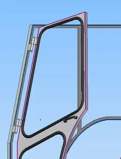
I have a simulation problem opening a door with an actuator.
the door is hinged on a frame that is not perpendicular to the base, but it is inclined to 15°, so the door as well as opening it rises.
I don't know what constraint to put the actuator to make a simulation.
I hope to have explained, however in the annex you find an image.
 

Attachments

  • Porta.webp
    Porta.webp
    18.7 KB · Views: 28
I don't know if I understand, but if you have to simulate the door that opens and closes, try to give a bond of degrees between the planes of the two parts of the hinge, I explain better: at closed door, create two parallel and coincident planes that pass through the axis of the hinges, one in the fixed part of the hinge (part on the mount) and the other in the part that will have to rotate (side door). creates a 0 degree bond between the two floors, animates the bond with the degrees you want, and you will see the door opening and rising simultaneously.
I hope I helped you! otherwise explain the problem better.
attach the pack and go
 
What am I doing?! :-)
apart from jokes, if you have an image or the pack and go would be better, I don't understand what the actuator is, are you referring to a gas piston? if you can help, bind the two bodies of the piston on the central axis, then create a point of work on the two ends, and bind them with other points created on the frames, in this way they are articulated as in reality. . .

If you put an image of the detail and maybe the pack and go I can try it directly...
 
I have to apply a gas spring with the winding head, you can't see in the image I posted because after several attempts I was sick of seeing her: eek:
 
Okay, I understand and I think I can help you, I use a similar system for the articulated heads, to see them on the move, I used the "win" I told you about.
I'll give you an example, and I'll give you a seat, okay? only one question: did the gas spring draw it in one ipt or are two bound parts that simulate reservoir and stem? to facilitate things I recommend you to insert in the set the two separate parts.. I'll make you an example file.
 
done:
Don't mind the little refinement of the design, I did it quickly and without taking care of the slightest detail, but I hope you understand well. here are the videos of the animation:
Open: http://www.youtube.com/watch?v=6wi2lecft-4chiudes: http://www.youtube.com/watch?v=ppvfmdkh29cand here is the file together with the components, take a look and see if it is useful.
do not mind how the details are drawn, or at least where I placed the piston (totally random...) focused on the constraints of the piston!

Let me know!
tree
 

Attachments

thanks alby189 your method works, for reasons of time I have inserted to the spring you posted, as soon as I finish this job I try to make it myself, I hope that if I have to have some disappointments to count on your help.:finger:
 
Well! of course if you need you can count on me, maybe for a live thing contact me on skype.
I made the gas piston completely randomly, it would be done with the real size, so you realize the bulk and everything.
Let me know!
 
if by actuator means a piston or even a gas spring, simply binds the two rods in such a way that the fixed one (cylinder) remains bound on the plane no a point-floor bond, so as to simulate a spherical snode. the same do on the door to fix what is the mocil part of the actuator (piston-tiff). at this point it is enough to give 2 constraints (concentric of the cylinder-tire and cylinder bottom plane and the plunger plane (co incident between two floors that is to simulate the race). so by animated this last bond the plunger will flow into the cylinder going to move your inclined door, which will follow the opening dictated by the rotation of the hinges.... .
If I hadn't solved your problem yet let me know... I could send you a file of assembly that simulates everything... remember the email...
Bionavians
 
Why not point? Have you seen the example I posted before? I think the result is the same, but obtained with two different methods... the point point leaves a total degree of freedom on the spheres, what happens in reality.
the beauty of these programs is that there are many ways to get around the problem, we found two, and one does not exclude the other.
tree
 

Forum statistics

Threads
44,997
Messages
339,767
Members
4
Latest member
ibt

Members online

No members online now.
Back
Top