• This forum is the machine-generated translation of www.cad3d.it/forum1 - the Italian design community. Several terms are not translated correctly.

who helps me in an extrusion? [press weapons]

  • Thread starter Thread starter Italo.Persechino
  • Start date Start date

Italo.Persechino

Guest
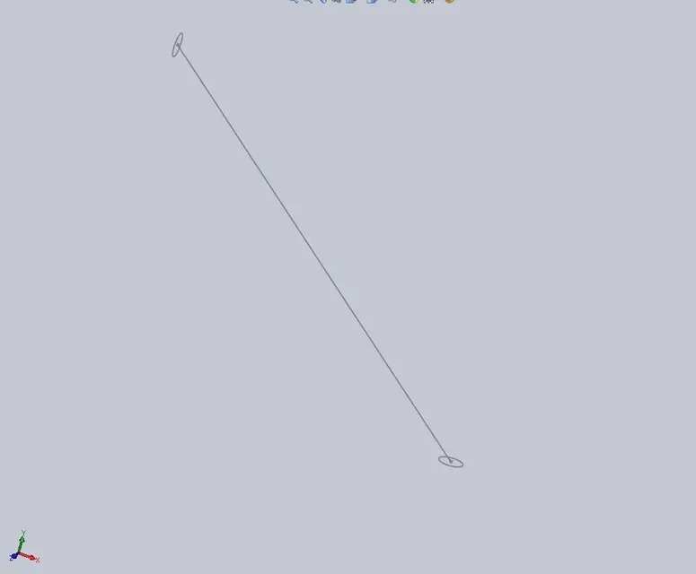
Hi guys, I'd like a help to create a circular section bar. the problem is that the axis is oblique and the faces at the end are on 2 different planes, here is the image:


the lower face is parallel to the xz plane, the upper one on the zy plane, the axis is on the xy plane.

Thanks.:biggrin:
 

Attachments

  • mifonp.webp
    mifonp.webp
    5.5 KB · Views: 32
Last edited by a moderator:
you can do with a loft: give as profiles the two circles and as line of half-carry your oblique line.
learned just yesterday on this forum eheh
ps: I attach you an illustrative file. . .
 

Attachments

remains the fact that the end sections are round and not the profile. Is that what you're getting?
 
to look at ghli sketches would seem a straight tube cut to "salame slice" on the sides.... So a linear extrusion plus two cuts.
 
Therefore, let us first understand what we want to achieve. There are several ways to get what you want.

Are the two end sections circumferences? (in this case the "tube" cannot be circular! )
Is the line a straight one? is orthogonal at least one diameter of the two circumferences?

Then

Do you need to perfectly respect the end sections?
Do you need to get a perfectly circular (or solid) section surface?

We must first answer these questions. in fact you could:
- make a surface (or solid) between the only two sections. so respect the sections, but do not guarantee that the piece is circular, nor constant, do not even guarantee that the axis is the one designed.
- loft with one section and the line. so you will respect only one section, do not guarantee neither that the tube will be circular, nor the absence of twists, but the sections will be all the same, and the axis will be that drawn.
- loft between the two sections and the line. so respect both sections, but do not guarantee the uniformity of section, not even circularity, not even the absence of twists. but guarantee the axis
- make a circular section tube (as explained by hunter) and cut in slice of salami the ends, so you will not respect the end sections, but you will ensure consistency and circularity of the section, lack of twists, cleaning of the surface (or solid). do not guarantee the axis, unless it is perfectly straight.

to choose a way to proceed you must know what you want to get. . .

It is obvious, but perhaps it is the case of underlining that in a surface like this, or the orthogonal sections, or those "salame slice" can be circular. Of course not both.
 
you can do with a loft: give as profiles the two circles and as line of half-carry your oblique line.
learned just yesterday on this forum eheh
ps: I attach you an illustrative file. . .
hi, the problem is that it tells me that the guideline does not intersect section no.1 :confused:
to look at ghli sketches would seem a straight tube cut to "salame slice" on the sides.... So a linear extrusion plus two cuts.
how to make cuts? I thought about it, but I don't know.

I'm really inexperienced. . .

thanks to all however;)
 
Therefore, let us first understand what we want to achieve. There are several ways to get what you want.

Are the two end sections circumferences? (in this case the "tube" cannot be circular! )
Is the line a straight one? is orthogonal at least one diameter of the two circumferences?

Then

Do you need to perfectly respect the end sections?
Do you need to get a perfectly circular (or solid) section surface?

We must first answer these questions. in fact you could:
- make a surface (or solid) between the only two sections. so respect the sections, but do not guarantee that the piece is circular, nor constant, do not even guarantee that the axis is the one designed.
- loft with one section and the line. so you will respect only one section, do not guarantee neither that the tube will be circular, nor the absence of twists, but the sections will be all the same, and the axis will be that drawn.
- loft between the two sections and the line. so respect both sections, but do not guarantee the uniformity of section, not even circularity, not even the absence of twists. but guarantee the axis
- make a circular section tube (as explained by hunter) and cut in slice of salami the ends, so you will not respect the end sections, but you will ensure consistency and circularity of the section, lack of twists, cleaning of the surface (or solid). do not guarantee the axis, unless it is perfectly straight.

to choose a way to proceed you must know what you want to get. . .

It is obvious, but perhaps it is the case of underlining that in a surface like this, or the orthogonal sections, or those "salame slice" can be circular. Of course not both.
hi, the bar should be assembled with other "pieces", we say that it goes to form the hypotenuse of a rectangle triangle, where however the caties are square section tubes, that's why the ends of this bar should be cut in that way, so that when I go to assemble I put "the accident" with the side face of the parallelepipedo (let's say in cateto to understand us) and with the end of the bar. .

I don't know if I explained, I'm sorry, but it's not my strong... :

However I believe the loft is the best solution, so I can respect the surfaces. ..but it turns me in the middle...:frown:
is it not the case of making the pipe for good (so to circular section) and cutting it with the faces of the parallelepipeds?
 
(cut)
I don't know if I explained
You explained yourself terrible.:cool:
I don't know if you saw the text flow that was written to try to imagine tu What do you need?
I'm sorry, but it's not my strong... :
It's good that you learn to explain yourself if you want to have a chance that your thesis is legible.

I also quote this in reading the crystal bowl and try to answer you.
if you need to make a circular section tube that at the ends intersects two floors:
1) create a plan in the middle point of the segment representing the axis of the pipe
2) on that floor create the sketch and draw the section of the pipe
3) make an extrusion of that sketch in two directions, choosing as a final condition of both directions "to the surface" and as a target surface select the arrival plans or the faces of the square section tubular. it takes two minutes dry without running, using one floor and one function, without complicating life with cuts, lofts and similar amenities for a straight tube.
 
You explained yourself terrible.:cool:
I don't know if you saw the text flow that was written to try to imagine tu What do you need?

It's good that you learn to explain yourself if you want to have a chance that your thesis is legible.

I also quote this in reading the crystal bowl and try to answer you.
if you need to make a circular section tube that at the ends intersects two floors:
1) create a plan in the middle point of the segment representing the axis of the pipe
2) on that floor create the sketch and draw the section of the pipe
3) make an extrusion of that sketch in two directions, choosing as a final condition of both directions "to the surface" and as a target surface select the arrival plans or the faces of the square section tubular. it takes two minutes dry without running, using one floor and one function, without complicating life with cuts, lofts and similar amenities for a straight tube.
You're right. I hope this image makes it clear.


the tube for now I have done it with loft, but I will also try your solution, thank you ;)
 

Attachments

  • 1125rhx.webp
    1125rhx.webp
    49.4 KB · Views: 14
Last edited by a moderator:
just to understand if it would be an additional method, but you could not get the result of the beginning photo discussion if you did the circular sketch on the right, you extruded it with the direction option using the previously sketched straight on the front floor passing through the center of the circle for example to 45° and for an approximate distance. once you get the bar you could cut the other end with extruded cut using a segment on the front floor.
so however you get the face cut in the form of slice of salami.
I threw it there. Hi.
 
Last edited by a moderator:
You're right, I hope this image makes it clear. .
perfect. . .
the tube for now I have done it with loft, but I will also try your solution, thank you ;)
You have to do it as I wrote, the loft for this pipe does not serve a pipe, it is the case to say:
extrude a profile created on the average plane of the tube axis. one feature and no cut.

ah, avoid inserting images as external links, you have to use the "allegati" icon
 
I think you should stop and make the tutorials in solidworks, you'll eventually earn it in time and learn to use it.
For example, such a frame should be made with welding functions and structural member.
 
You explained yourself terrible.:cool:
I don't know if you saw the text flow that was written to try to imagine tu What do you need?

It's good that you learn to explain yourself if you want to have a chance that your thesis is legible.

I also quote this in reading the crystal bowl and try to answer you.
if you need to make a circular section tube that at the ends intersects two floors:
1) create a plan in the middle point of the segment representing the axis of the pipe
2) on that floor create the sketch and draw the section of the pipe
3) make an extrusion of that sketch in two directions, choosing as a final condition of both directions "to the surface" and as a target surface select the arrival plans or the faces of the square section tubular. it takes two minutes dry without running, using one floor and one function, without complicating life with cuts, lofts and similar amenities for a straight tube.
Aoh! !
Kill the old man, he understands a dog!
and I thought the keyboard used it so as not to lose pencils!

:biggrin:
 
You explained yourself terrible.:cool:

I also quote this in reading the crystal bowl and try to answer you.
if you need to make a circular section tube that at the ends intersects two floors you must:
(1)
(2)
(3)
Aoh! !
Kill the old man, he understands a dog!
and I thought the keyboard used it so as not to lose pencils!
:biggrin:
but no, it is that here at the nursing home, in the computer room, we have particularly good caregivers who can translate into Italian what we bofonchiamo between a change of diapers and the other:tongue:
 
perfect. . .

You have to do it as I wrote, the loft for this pipe does not serve a pipe, it is the case to say:
extrude a profile created on the average plane of the tube axis. one feature and no cut.

ah, avoid inserting images as external links, you have to use the "allegati" icon
Thank you so much, I tried to do it with your method and I think it was the best solution, thank you so much! ;)

Since you're very experienced, what if I try to use this other partner's solution, too? Do you think it's better?
I think you should stop and make the tutorials in solidworks, you'll eventually earn it in time and learn to use it.
For example, such a frame should be made with welding functions and structural member.
Now I try with this solution, but I would like to use profiles of sizes other than standard ones, is it possible?
 
I think you should stop and make the tutorials in solidworks, you'll eventually earn it in time and learn to use it.
For example, such a frame should be made with welding functions and structural member.
Hi! I tried to do as you told me, I followed the welding tutorial and I took 2 seconds. But I have to perfect several things!

I wanted to ask you:
-but when you connect between them 2 elements these are automatically welded or to join them I must always make a soldering bin?
-I wanted to use simulation express on the structure by binding the back and applying forces to the front to measure the torque stiffness, the problem is that it tells me that there are multiple bodies in the part and that I have to select only one at a time... is it possible to make the whole structure become a single part?

Thank you.

I train what I did
 

Attachments

....the bar must be assembled with other "pieces", we say that it goes to form the hypotenuse of a rectangle triangle, where however the catets are pipes with square section.. .
If I understand what you mean,
among the many ways you can also use the welding/framework/structural dimensions functions; simple and fast. .

of course always help and guide, help and guide, help and guide, help and guide........ :biggrin:
the simple basic functions, all explained in the program. and do the tutorials.

greetings
Mar
Sorry, I read late and responded to the flight..
I see you're already doing what I suggest:

greetings
Marco:smile:
 
you can do all the profiles you want also because in the solidworks library there are 3 on the cross.
 

Forum statistics

Threads
44,997
Messages
339,767
Members
4
Latest member
ibt

Members online

No members online now.
Back
Top