maxopus
Guest
ok ... visto.
See, thank you.Good evening to all,
what maxopus writes about thinkdesign is right if we talk about thinkdesign v. 9.0 of 2003. I am pleased to refute what is indicated with a video that shows that relationships are kept compared to the features inserted
http://www.megavideo.com/?v=j3rub90x
the top/down modeling is very little if not used correctly with the help of skeletons.See, thank you.
But I continue to wonder, thinking about the design of real objects and not academic exercises, what it takes to have a set with a suspended component in the vacuum or connected to geometry that no longer exists.
I will be "gnucco" :redface: but it seems more a wandering mine than an added value.
do you have concrete examples to make me where this "power" of pro-e and tink3 serves during design, taking into account that if you have to lean on reference geometry for top-down modeling you can use plans, sketch 2d/3d, or entire hidden parts of support?
Hi.
the top-down modeling I know and use it intensely and I assure you that it succeeds well with swxthe top/down modeling is very little if not used correctly with the help of skeletons.
simple driving sketches that drive you a whole machine give you an advantage not indifferent, without talking about the propagation of cascading parameters.
") so I am quite clear what the skeleton is, that it is 2do 3d.
so I am quite clear what the skeleton is, that it is 2do 3d.when you pass by modena you are welcome; if you have to come specifically decline any responsibility on the outcome of the commercial operation. . :biggrin::wink:If you want, I'll come and make you a demo. :wink:
Okay, no, because sometimes there's an abstract concept of top-down.the top-down modeling I know and use it intensely and I assure you that it succeeds well with swx
I am not clear on the other hand the usefulness of maintaining the bonds between the parts compared to the geometry erased in the course of the modeling and finding myself with the parts of the axieme floating in the vacuum as in the example video with tink3. if the ageometria has been erased (or absorbed by new features) is because in the finite part, the one that comes out from the workshop, that geometry does not need therefore precisely does not exist. explain why but especially when it has to become a reference for an assembly bond?
when you pass by modena you are welcome; if you have to come specifically decline any responsibility on the outcome of the commercial operation. . :biggrin::wink:
Hi.
it is too hot to start a flame; Is it okay if we get back in the fall? :biggrin:. .Okay, no, because sometimes there's an abstract concept of top-down.
I do not doubt that it works well with swx but clearly with proe is better.:tongue:
probably it is not unstable if the cad is in mind the coordinates of the reference geometry modified by the next features. for the moment I find it useless, as if on I had the possibility while working on the surfaces to "feel" still the trimmed geometry.As for videos, I absolutely do not like that methodology of work, frankly it is very unstable, any cad you use...
go for lunch recommended by me and paid by you. at the bottom you are looking for a potential customer and from what modno is world are suppliers to pay lunches and dinners:tongue:ok for modena, quiet enough me a nice lunch in a nice place recommended by you that I know you are of good fork.
a choice of who designs the software determines to what level of "annidation", if you pass me the term, the software must keep cocnto of geometry generated. If you think about it with any parametric cad (at least I hope...) you can start modeling a new part in the context of an axis by supporting the first sketch to the surrounding geometry. in the course of the modeling of that part if the solid generated by that first sketch is also heavily modified however external references are maintained. probably it is a design choice of the various software houses to establish that in the assimis as in the case that we have seen, relationships are maintained if the geometry that generated them is maintained, worth being with parts that you do not understand well what they are attached despite not generating apparent errors.I wanted to show you the differences between ways of conceiving geometric topologies according to the cad used.
are two different ways of conceiving generation and relationships between geometric entities
I have the right path would be a warning that asks what you want to do as a big:smile: and at least advise you to move the coupling from a corner, that your miller will so much pull away by making a nice bevel, to an existing face in the finished piece and ready for assembly in the workshop.However, you will agree with me that by applying a rounding or a bevel ... it is better if any pairings remain there where they are without failing.
Okay, it's clear to me, just that I don't understand, specific case, the usefulness of maintaining relations with respect to gemetria erased during modeling with all the risks to this connected, because if for example add a feature that removes the material from the right side where there were assembly references and the software does not signal it really risk to regenerate a joint that then in the workshop will present assembly problems. I don't talk about a voragine in the middle of the machine or a bearing that floats in the vacuum, but maybe two separate plates of 1 mm, which then don't give you interference if you do the control but maybe they escape you in a total of 4-5000 parts. This is an example of contraindication of this way of managing the bonds of assemblies. I just can't think of advantages. I'm sorry, but at this time I'd like to make temperacaxxi, so I'd like you to make me some examples where you need to bind to geometry that will be removedsome fall into the effectuating of the couplings recognize a surface or a corner of that form (which is very easy to manage and very flexible but at the risk of instability as you go to make a change), other cads (as pro/e) attribute an identity to every geometric entity generated (a very stable solution from the point of view of the relationships with the limit that is to be used with raziocinio and not to dog caxo).
Let's say that having no problems axioms of that size depends mainly on the handle of those who made it, not on the software. for lovers of circular references of penis-based design there is no pro-e that keepEach of us can prefer one or another as a system, I have learned with time to appreciate the method used by pro/e because when I manage assiemi by tens of thousands of components it is beautiful to regenerate and not even have a failure to settle.
I don't like to have the thought that a simple rounding can create problems.
Your problem is, you've been using a context cad for years.Why should the model be "winned" according to the "proprietary" rules of the cad in use and complying with the methodology and whim of the designer making it difficult if not impossible to understand and intervene later to other designers?
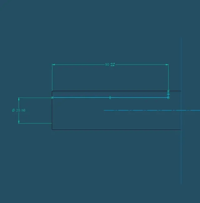
I take the cue from the images that published hunter epr emphasize that using well a parametric cad (I take as reference proe) it is possible to do what "er president" hopes, that is to quote as would be a drawing... When I was doing proe courses, it was one of the things I emphasized: dimensional thinking also in the table.I add a couple of exemplary images.
I saw the video. to insert those quotas and make specular the holes of a already made part you took 3 and a half minutes. with a parametric cad, looking at the 2d quoted that piece you do it from zero in 2 minutes and then check All size, not just those three. Given the time of recalculating the changes you applied, I wonder what happens if you parameterize more strongly (as long as it is possible and convenient) a complex model as a fusionthere is to say that you can also do with an explicit (see "spaceclaim... parametric?" in the sc section), more than anything else is a question of "manic"
 to more or less salty subscription shots and with the certainty of not being able to return to using the cad of the year before.
for me the parametric area is minata and I move with circumspection, but I have to declare parallel two lines on a profile to have the parallel faces of the generated solid and then I have to put the symbol of parallelism on the 2d design, to me it seems to work on the reverse.I saw the video. to insert those quotas and make specular the holes of a already made part you took 3 and a half minutes. with a parametric cad, looking at the 2d quoted that piece you do it from zero in 2 minutes and then check All size, not just those three. Given the time of recalculating the changes you applied, I wonder what happens if you parameterize more strongly (as long as it is possible and convenient) a complex model as a fusion
changes on an imported piece you would definitely have made them faster with your own and peculiar tools of a contextual. Of course, if you tell me that you can reshape the flight as much as you quoted then I tell you you needed a parametric and not a contextual.
It seems to me that the various softwre houses are sailing a bit. for now there are the contextuals that sketch out some control of the geometry guided by quotas but are light years away from the top-down modeling of a parametric, while some parametric have direct modeling functions that however generates feature, therefore always histoy based, while others as if they have direct and parametric modeling that however can not coexist and if steps from that parametric to the direct then do not turn back
I would say many ideas and equally confused, and users down to beta tester or better market-tester, or better marketting-tester
I care about the paxxes.
Hi.
Okay, perfect for quotas, but I would like to see in 3d that attachment.I add a couple of exemplary images.
You don't have to do that, in 95% of cases the cad automatically does.for me the parametric zone is minata and I move with circumspection, but I have to declare parallel two lines on a profile to have the parallel faces of the generated solid
no, if you have to change a project, the table doesn't open it, do everything in 3d, clearly if ilc has the appropriate tools to do it and doesn't force you to make a "measure 3d" every two clicks. in solid edge I go on the feature, I do "dynamic change" and here I appear the odds to change.If I did not participate in the study together with the development team of the cube, I must change the project of the cube, read the 2d (or the corresponding labels of the 3d) and know how it was bound and how I have to act to change it.
the problem arises from poor models for laziness/incompetence, certainly not from the fact that the design tools are lacking, because they are not.some are looking for internal roads (the chunk he was talking about) and others are beating the dm road, dt or how the hell you want to call it, simply to give the chance to those who have to work on unknown parts to be able to work.
It is already so largely, except for the tolerances of form that have purpose of testing and not modeling where geometries are exact by definition.the thing is confusing and users are a bit disoriented but, in my opinion, the main road to follow could be the one that we all know gd&t, if we establish that a 2d design that represents a physical model, is perfectly represented and bound by gd&t, I don't understand why not use the same tool even in 3d.
from this base you could start with the parameterization, but it would be a Esperanto with which everyone could compare.
I didn't understand the question well.Okay, perfect for quotas, but I would like to see in 3d that attachment.
the piece is bound in a unique and clear way, if in 3d I had the same tools I could bind in an "international" way, regardless of the cad.
I have not understood very well what you mean; like something like that, or quote directly in 3d?Okay, perfect for quotas, but I would like to see in 3d that attachment.
the piece is bound in a unique and clear way, if in 3d I had the same tools I could bind in an "international" way, regardless of the cad.
p.s.: the pdf file is a bowl, I link directly to wiki:http://en.wikipedia.org/wiki/geometric_dimensioning_and_tolerancing
I intend to quote directly in 3d with the automatic attribution of constraints.I have not understood very well what you mean; like something like that, or quote directly in 3d?
http://rapidshare.com/files/272320325/quote.jpg.html