ector
Guest
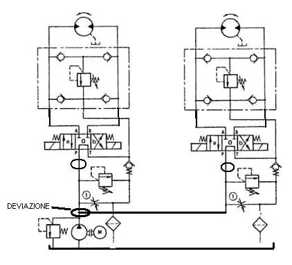
Hey, guys, I have to make a plumbing circuit, could you help me do it?
I basically have to turn a hydraulic motor (in both directions of rotation) that must win a pair of 30 nm, at a speed of 250 rpm.
I have to connect it to a 24V powered electric motor.
I thought of the following scheme:
electric motor-joint- hydraulic pump- distributor- hydraulic motor.
My question is:
Where do I put the various valves?
What pressure does it work?
how can I gradually control the speed of the hydraulic motor?
If you can help me, I'd be grateful