
You are using an out of date browser. It may not display this or other websites correctly.
You should upgrade or use an alternative browser.
You should upgrade or use an alternative browser.
Pastorman75
Guest
I'll be like the "sphinx", answering with a question:
what stress is present in the material when the pressure cylinder arrived at the maximum extension and supports in elevation the load?
what stress is present in the material when the pressure cylinder arrived at the maximum extension and supports in elevation the load?
AngeloB
Guest
AngeloB
Guest
for pasteurman
the piston of the last stem is diam.63
therefore indicative
p= 900/((pi/4)*6.3^2)= about 29 bar
the piston of the last stem is diam.63
therefore indicative
p= 900/((pi/4)*6.3^2)= about 29 bar
Pastorman75
Guest
apart from the last section "full" of the cylinder, under equilibrium conditions and at the maximum extension, the walls of the hollow cylinders, are subjected to a "normal" stress nothing since it is the pressure oil column that supports everything "pushing" the two bottoms.
Obviously the walls will be subject to a circumferential tension not anything caused by the pressure.
beyond the equilibrium condition, that is, with pressure greater than that necessary to balance the load, the walls of the hollow sections are subjected to traction and not compression.
Therefore, a possible check at peak load, should be made only on the last part of the piston, the full one.
Is he coming back?
Obviously the walls will be subject to a circumferential tension not anything caused by the pressure.
beyond the equilibrium condition, that is, with pressure greater than that necessary to balance the load, the walls of the hollow sections are subjected to traction and not compression.
Therefore, a possible check at peak load, should be made only on the last part of the piston, the full one.
Is he coming back?
AngeloB
Guest
If I understand correctly you mean that where there is pressure oil there is no peak load.
and something I thought about, but there was no way to prove it.
doing the verification, not considering the plumbing aspect, thinking the rods blocked "mechanically" I think I'm on the security side.
and something I thought about, but there was no way to prove it.
doing the verification, not considering the plumbing aspect, thinking the rods blocked "mechanically" I think I'm on the security side.
Pastorman75
Guest
Yes, where the material is "teso" there is no danger of instability to cover.
to prove it uses the eq. cardinals of the static to a sistama made by two solo telescopic elements.
Say hi.
to prove it uses the eq. cardinals of the static to a sistama made by two solo telescopic elements.
Say hi.
Messerschmitt
Guest
I understand that.apart from the last section "full" of the cylinder, under equilibrium conditions and at the maximum extension, the walls of the hollow cylinders, are subjected to a "normal" stress nothing since it is the pressure oil column that supports everything "pushing" the two bottoms.
Obviously the walls will be subject to a circumferential tension not anything caused by the pressure.
beyond the equilibrium condition, that is, with pressure greater than that necessary to balance the load, the walls of the hollow sections are subjected to traction and not compression.
Therefore, a possible check at peak load, should be made only on the last part of the piston, the full one.
Is he coming back?
But I would like to make an observation: In my opinion the seals and seals of the plunger and the stem are a point that could be easily deformable. In other words, even if the stem and shirt remain straight, they could still form a break with the edge placed at the point where the stem enters the cylinder. at this point the static scheme changes and I do not think that it is enough for the internal pressure to prevent instability. What do you say?
Pastorman75
Guest
I don't want to, but you have an incorrect static pattern in mind.
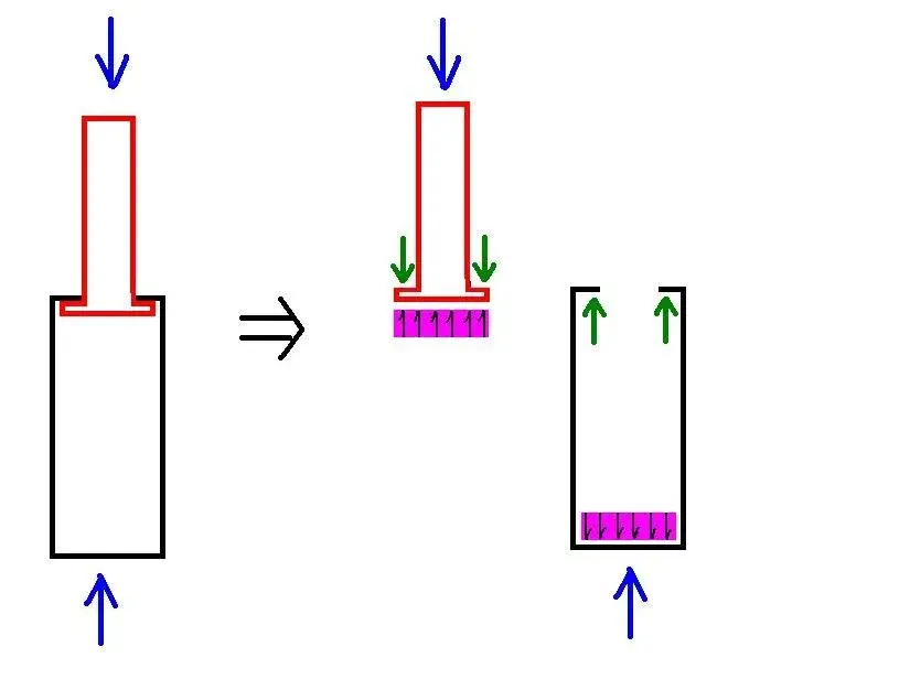
think of a simple cilider; when the oil pressure exceeds the value necessary to lift the load and cylinder is at its maximum extension, it turns out that:
- the stem is compressed
- the shirt (or cylinder) is tense
- the cylinder case is compressed
I attach a sketch.
Hi.
think of a simple cilider; when the oil pressure exceeds the value necessary to lift the load and cylinder is at its maximum extension, it turns out that:
- the stem is compressed
- the shirt (or cylinder) is tense
- the cylinder case is compressed
I attach a sketch.
Hi.
Attachments
Messerschmitt
Guest
I understood the static scheme, maybe I explained badly in making observation.I don't want to, but you have an incorrect static pattern in mind.
think of a simple cilider; when the oil pressure exceeds the value necessary to lift the load and cylinder is at its maximum extension, it turns out that:
- the stem is compressed
- the shirt (or cylinder) is tense
- the cylinder case is compressed
I attach a sketch.
Hi.
I don't have much knowledge of oleodynamics.
My perplexity lies in the fact that, from the reasoning you have exposed, it seems that it is possible to build cylinders with very long and slim lines, because only the last vent is subject to peak load.
your reasoning line and is certainly right, but I would say that you do not consider any other phenomenon that could affect the maximum length of these multi-swire cylinders. I therefore thought of the effect that can have seals and seals when the cylinder is completely extended. I think about the limit case, with garnishes with a lot of game, which may not guarantee that the stem and shirt remain coaxial.
Pastorman75
Guest
Perhaps the misunderstanding lies in the hinges that are in the head and tail to the cylinder. in the scheme are ideal hinges and without friction.
cannot be born bending under these conditions and therefore there is no risk of loss of coaxiality for intermediate shirts since they are stretched and not compressed.
the last seal is the one that determines the value to be assigned to the free length of inflection "lo"
in the calculation of stability for the spherical utim (compressed because full), you can consider the free length of inflection as if:
- the seal was a hinge.
- the load attack a vertical cart.
look at the table and see when it is "the" free length of inflection.
Hi.
cannot be born bending under these conditions and therefore there is no risk of loss of coaxiality for intermediate shirts since they are stretched and not compressed.
the last seal is the one that determines the value to be assigned to the free length of inflection "lo"
in the calculation of stability for the spherical utim (compressed because full), you can consider the free length of inflection as if:
- the seal was a hinge.
- the load attack a vertical cart.
look at the table and see when it is "the" free length of inflection.
Hi.
Pastorman75
Guest
I checked.
lo = l for a rod bound with 2 hinges at the extremes
It's our case.
lo = l for a rod bound with 2 hinges at the extremes
It's our case.
bisogna_rimanere_umili
Guest
Has anyone ever faced such analytical problem?
i.e. having a telscopic cylinder or a beam with non-continuous section loaded axially and verify whether the chosen section is sufficient to avoid the transfer for peak load?
to me it seems that there is something that allows to calculate the lungh of free inflection for every part, but I do not remember where and especially if I did not dream of it. . .
i.e. having a telscopic cylinder or a beam with non-continuous section loaded axially and verify whether the chosen section is sufficient to avoid the transfer for peak load?
to me it seems that there is something that allows to calculate the lungh of free inflection for every part, but I do not remember where and especially if I did not dream of it. . .
meccanicamg
Guest
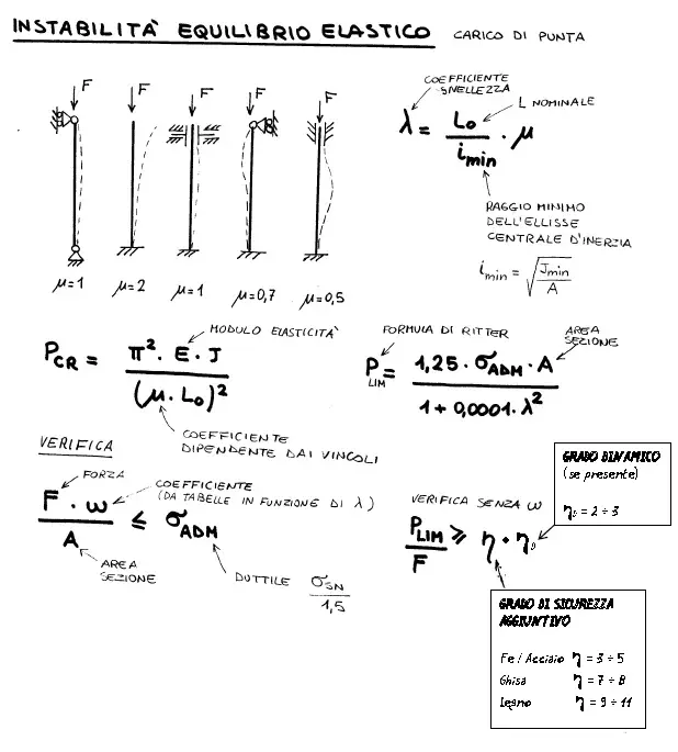
You need this one I've attached. verifiable in cnr uni 10011 (retired in 2004) and eurocode 3.Has anyone ever faced such analytical problem?
i.e. having a telscopic cylinder or a beam with non-continuous section loaded axially and verify whether the chosen section is sufficient to avoid the transfer for peak load?
to me it seems that there is something that allows to calculate the lungh of free inflection for every part, but I do not remember where and especially if I did not dream of it. . .
Let's say that having a different section multistage cylinder you could do the overlap of the effects, analyze each piece of spherical and calculate the single shift. then join the bands until you find the total.
or calculate average section and consider it unique beam.
Remember that there are adequate oversized coefficients.
Attachments
bisogna_rimanere_umili
Guest
I would simply consider the whole stem of size equal to the smallest/periculous section (and then it would go oversize the whole) and then I would go to apply the "usual" verification of which you have returned a branch.. .You need this one I've attached. verifiable in cnr uni 10011 (retired in 2004) and eurocode 3.
Let's say that having a different section multistage cylinder you could do the overlap of the effects, analyze each piece of spherical and calculate the single shift. then join the bands until you find the total.
or calculate average section and consider it unique beam.
Remember that there are adequate oversized coefficients.
what do you mean by overlaying effects?
If you mean what I think I know there would be doubts/problems to assign to each section the coefficient "mu"...

meccanicamg
Guest
by reasoning above are all with the 3rd scheme with mu=1 because it is considered that at stem out in pressure you get a recess due to the pressure of the greater section than the next while the upper section free iterato for n sfli. then you can reason differently but first caught could be so. as much as the whole unique beam with schema 3. I'm pointing out if you have a simulator modeler like swx cosmos set the point load analysis and you're appropriate as further verification.I would simply consider the whole stem of size equal to the smallest/periculous section (and then it would go oversize the whole) and then I would go to apply the "usual" verification of which you have returned a branch.. .
what do you mean by overlaying effects?
If you mean what I think I know there would be doubts/problems to assign to each section the coefficient "mu"...