
• This forum is the machine-generated translation of www.cad3d.it/forum1 - the Italian design community. Several terms are not translated correctly.

rotazione parti 3d

  • Thread starter Thread starter lustro
  • Start date Start date

lustro

Guest
hello to all, I spuled around with the search command, but nn I found answer to my quaint: in the environment together (and maybe part) there is a command that allows to rotate the assemblies (part) of certain predefined degrees? ?
I know that you can set sw in such a way that at every pressure of the arrows of movement correspond certain degrees of rotation, but nn there is something more practical :smile: ? for example, if I realize a set (or part) and then in the table I realize that I need a certain visual angle, I would like to create it and then save it in the bar of the tools of orintment (the one that appears clikkating on the bar
in the table environment if I use the rotation command, a shutter opens in which asks how many degrees turn the view: Well, I'd like to know if you have something similar in the environment together and part.

Thank you all!
 
in the table environment if I use the rotation command, a shutter opens in which asks how many degrees turn the view: Well, I'd like to know if you have something similar in the environment together and part.

Thank you all!
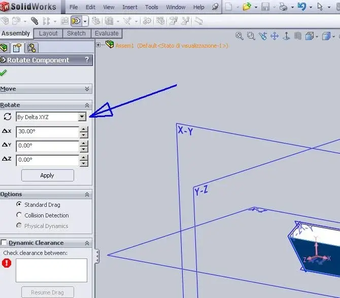
I found the command to revolve around the three Cartesian axes, but not around a corner to please.
 

Attachments

  • ruota.webp
    ruota.webp
    38.2 KB · Views: 28
I tried to use the command you suggest, but if the axieme is totally defined, nn makes me move anything....and to the limit it moves/rolls only the elements nn completely fixed.

I look for a command that rotates everything, but that does it in a controllable manner (which to rotate with the mouse nn is that it is particularly accurate.... my precision [e quella del mouse] leaves much to be desired)
 
create a tilted plane as much as your rotation must be, once created, put yourself to normal, then press the space bar and save the view
that you see at that moment.
going to the table, you can call back the view just saved.
 
I tried to use the command you suggest, but if the axieme is totally defined, nn makes me move anything....and to the limit it moves/rolls only the elements nn completely fixed.

I look for a command that rotates everything, but that does it in a controllable manner (which to rotate with the mouse nn is that it is particularly accurate.... my precision [e quella del mouse] leaves much to be desired)
If the axieme is totally defined, it's obvious (and right) that you don't turn it... .

What you can do is redefine the orientation of the first part and hope that the others, linked to this, move consistently.
 
create a tilted plane as much as your rotation must be, once created, put yourself to normal, then press the space bar and save the view
that you see at that moment.
going to the table, you can call back the view just saved.
a little laborious, huh?? but thanks to the advice and I consider it
If the axieme is totally defined, it's obvious (and right) that you don't turn it... .

What you can do is redefine the orientation of the first part and hope that the others, linked to this, move consistently.
My nn wants to be a redefine the relationships of assemblies, but (more simply or at least I hope :finger:) turn everything around the point of origin (and if I have to rotate axes or references, I will rotate them too, it is not a problem)
and first I tried to redefine, compared to the main plans, the first part on which the others are based, but nn brought me to nothing, perhaps because for some components I was based on the same plans and therefore went in crisis when it was about to redefine the whole:frown::
 
I think there are not many other alternatives. create a plan from which to look in the part or together or simply if you can take reference surfaces parts from the table, insert view, relative to the model, high quality, steps to the solid model, select two faces and press on ok, click in the table space and you have the desired orientation.
 
a little laborious, huh?? but thanks to the advice and I consider it


My nn wants to be a redefine the relationships of assemblies, but (more simply or at least I hope :finger:) turn everything around the point of origin (and if I have to rotate axes or references, I will rotate them too, it is not a problem)
and first I tried to redefine, compared to the main plans, the first part on which the others are based, but nn brought me to nothing, perhaps because for some components I was based on the same plans and therefore went in crisis when it was about to redefine the whole:frown::
always prefer the "real" couplings in the axieme, especially to have the real constraints, to be able to move things according to a real sense, to make real assemblies as if you were at the mounting bench you (Always ask if you can premount this and that and then put it on the other).
 
I confirm what said by mike and mechanicalmg.
in the table insert the views you save in the model and to create a view or save a state created with mouse and keyboard rotations or refer to model geometries. I don't see what other way this could be possible.
 
a little laborious, huh?? but thanks to the advice and I consider it
hard? ?
it takes a little more than a minute... (if you have manual skills in creating plans... If not it takes less... )
However it is not a "artifice" (artifizio) but a standard modus operandi, I do not see the difficulty.
 
I know that you can set sw in such a way that at every pressure of the arrows of movement correspond certain degrees of rotation, but nn there is something more practical :smile: ? for example, if I realize a set (or part) and then in the table I realize that I need a certain visual angle, I would like to create it and then save it in the bar of the tools of orintment (the one that appears clikkating on the bar
boh, maybe I didn't understand what you need, but if you create a view by turning the model (arrow keys, mouse, references etc) and then pressing the space bar saves it in the list of views then that view you find it available in the guidance toolbar and when you make the table you have it in the list of views available in the design view feature manager in the "orientation" menu exactly as you asked.
easier than so...
 
boh, maybe I didn't understand what you need, but if you create a view by turning the model (arrow keys, mouse, references etc) and then pressing the space bar saves it in the list of views then that view you find it available in the guidance toolbar and when you make the table you have it in the list of views available in the design view feature manager in the "orientation" menu exactly as you asked.
easier than so...
in fact a subterfuge I often use is to set in
options the rotation degrees I need in that fringe, then reset the default value.
I learned this method using various cams... and it's a great system.
 
hard? ?
it takes a little more than a minute... (if you have manual skills in creating plans... If not it takes less... )
However it is not a "artifice" (artifizio) but a standard modus operandi, I do not see the difficulty.
is part of everyday things or almost
 
thanks to all for the suggestions received.

I will exploit the create plans and then save the views in the orientation bar and then call them back to the table.
 
the problem of the axes is not only relative to the view that apparently the solid is rotated, but if the program means it with numerical calculations always in the original axes are pains for those who then have to import it in a soft cam .
I'll explain better.
we put that with solidworks (an old version 2001 of the faculty where I studied) design a bowl the upper part is concave while the lower one is convex , if lamb the crude (material to work for example a parallelepiped of raw wood ) on a pantograph 3 axes and work the upper part concave I have no problems , after rotated the bowl emi you need the bottom soldile
therefore it serves a real rotation of the piece on a board as if the piece was created on those axes on solidworks, they serve two drawings one with the concave part on +z and one with the always concave part on -z.
I tried to rotate it on solidworks also from the primary lines that generate the sketch but in the end the cam always sees the original coordinates prevents the processing, I can not reconstruct it I would lose the zeroing,
on the soft cam idem, even if I roar the piece I can not work it the tool is not correctly positioned on the work surface, I press that it is a thing for pure personal knowledge but with this problem there are behind 2 weeks and still I have not managed to solve himself becoming a nightmare:-) hehehehehehehe.
greetings
 
Regardless of the cad used, I think that in these cases the best thing is to create an alternative axle to the original with the z axis in the opposite direction.
then expose the file to the new terna.
 
The first stupidity I think is:
1crei the rotation axis
2 circular recetition of the body around the axis
3vai in the function tree and between the solid bodies delete the original one and preserve the repetition.
at this point if you want you can create two configurations one with the only original body and another with the only repetition.
 
the problem of the axes is not only relative to the view that apparently the solid is rotated, but if the program means it with numerical calculations always in the original axes are pains for those who then have to import it in a soft cam .
I'll explain better.
we put that with solidworks (an old version 2001 of the faculty where I studied) design a bowl the upper part is concave while the lower one is convex , if lamb the crude (material to work for example a parallelepiped of raw wood ) on a pantograph 3 axes and work the upper part concave I have no problems , after rotated the bowl emi you need the bottom soldile
therefore it serves a real rotation of the piece on a board as if the piece was created on those axes on solidworks, they serve two drawings one with the concave part on +z and one with the always concave part on -z.
I tried to rotate it on solidworks also from the primary lines that generate the sketch but in the end the cam always sees the original coordinates prevents the processing, I can not reconstruct it I would lose the zeroing,
on the soft cam idem, even if I roar the piece I can not work it the tool is not correctly positioned on the work surface, I press that it is a thing for pure personal knowledge but with this problem there are behind 2 weeks and still I have not managed to solve himself becoming a nightmare:-) hehehehehehehe.
greetings
try to give an eyetip here:
http://www.cad3d.it/forum1/showthread.php?p=211203#post211203I hope this is the right solution. :smile:
 

Forum statistics

Threads
44,997
Messages
339,767
Members
4
Latest member
ibt

Members online

No members online now.
Back
Top