• This forum is the machine-generated translation of www.cad3d.it/forum1 - the Italian design community. Several terms are not translated correctly.

diet a pilot in the eye

  • Thread starter Thread starter warburg
  • Start date Start date

warburg

Guest
hi, I posted this question in the contestant forum of cad 3d, but without receiving answer; I deduce that he was too stupid and since I am more in confidence with you I announce that you can tell me without too much remore:biggrin::finger:

It's a perfect beginner question, but if I weren't, I wouldn't need to do it:wink:

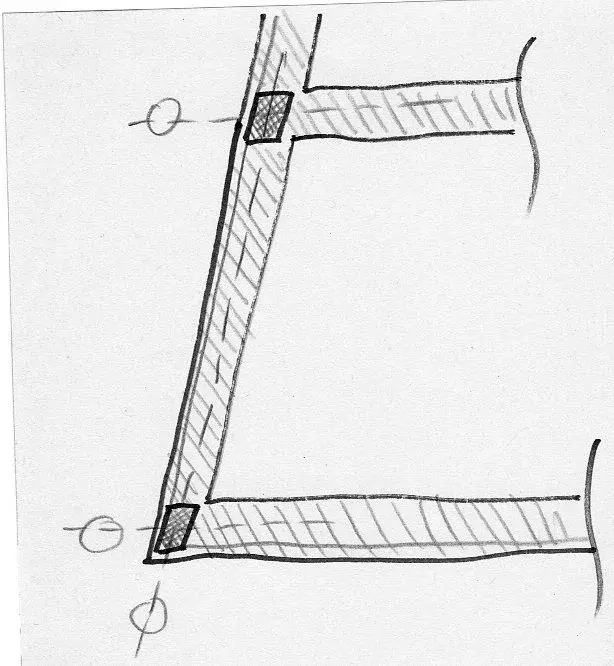
"... I would like to ask you how to do, if you do, to insert structural pillars in c.a. similar to those you see in the sketch attached. Let us suppose that a certain constructive and/or compositional need leads me to have to insert structural points inside the buffer walls and that the latter must have variable geometries not orthogonal, how do I get pillars that in the plant are skewed?
the example is a little forced, I need to understand; I know that for example the upper one can easily be replaced with a rectangular or square profile, on which will arrive a beam with inclined direction etc., but understand the purpose of my question :-)
Do you have to make a pillar family by changing one existing from time to time, based on project geometries?
I don't even do the strutturist, but I'd like to understand. "

Hi.
C
 

Attachments

  • x219.webp
    x219.webp
    60.3 KB · Views: 22
Last edited by a moderator:
the pillars, are elements based on line (in fact an extrusion on path) and therefore, in general, easily modified by appropriate modifications to the basic family.
However, in my opinion, additional characteristic elements have been added to these families (such as values relating to inertia and resistance modules), which can be easily "tabellated" in a constant section pillar (see for example metal pillars), while in a variable section pillar they must be recalculated from time to time.
remember that the parameters (default) of the families, are used by the "computer engine" of the sw to make it "parametric" and must be "maintained" carefully.
leave them to the user's discretion, if not properly charged (the parameters, not the dimensional data) could cause problems to the management that is carried out by the internal motor of the sw.
for this reason, I believe that the default structural pillars are traced back to "sections with constant shape", as in fact happens for the walls.
 
Thank you. I mean, pier luigi nervi would not have used revit!
joke, however I would be curious to understand one more thing following your comments: if I needed it anyway, if I still had the need to draw one or more supports from the uneven profile, as I must... Adjust me? I always talk about the environment revit arch, of course.
For example, project often in the ecclesiastical sphere, and can easily happen to have need to draw even very important pillars, whose profile very often is not a simple rectangle or circle. with what instrument can I do it in revit arch.? masses? new family?
Hi.
C
 
no, you can do quietly at the architectural level, modifying the existing pillars, or through a new family of structural pillars.
However, the addition of additional parameters (structural) where present, must be managed "manually" for each created family (if possible).
As a result of this, while at the level of "architectonic parameters" one can create the desired forms, at the level of "structural parameters " there are limitations.
keep treacherous that the structural pillars, are managed "completely" in revit structure.
Therefore, the structural calculation must be managed with structure and relative calculation programs (e.g. robots) - which I do not use -, which, starting from the forms (and structural parameters) inserted through the family, provide the relative size.

If you want to report the same speech on the energy side, I remember that it is possible to deal with an energy calculation mediated attribution of energy parameters to the structures (hard windows only).
a model (from gjiom, if not erro) that required the allocation of "data" to the individual elements; while a model had been developed by edilclima, which had developed, through the use of the bees of revit an external application that "acquired the thermal parameters of the structures" through the use of families of structures provided by edilclima, and then processed the data themselves with an external motor (application) revit.
Basically:
- you can create a structural pillar of any architectural form
- you can assign to the same structural parameters, according to the needs that require the specific family for subsequent use in structural calculation, exported to external sw (by using bees)
Unfortunately, for my knowledge of revit, in the specific topic I cannot go beyond.. .
 
no, you can do quietly at the architectural level, modifying the existing pillars, or through a new family of structural pillars.
However, the addition of additional parameters (structural) where present, must be managed "manually".
As a result of this, while at the level of "architectonic parameters" one can create the desired forms, at the level of "structural parameters " there are limitations.
keep treacherous that the structural pillars, are managed "completely" in revit structure.
Therefore, the structural calculation must be managed with structure and relative calculation programs (e.g. robots) - which I do not use -, which, starting from the forms (and structural parameters) inserted through the family, provide the relative size.
All right, I should have understood. we know that there is revit structure, absolutely, and in fact I do not intend to draw pillars or beams to be calculated personally, but only to draw pillars or beams that - then - can be calculated, or with structure or with what will be according to the strutturista. I would like to do in revit the same thing that I do in autocad, that is to draw (with some awareness) the form of the object that I imagined, and then pass everything to the strutturista, to recep the indications, possibly to go back and to better specify the form, and so on. considering that revit is a bim, I know that it will not be the same thing that with autocad, obvious, but the difference I imagine is better, not worse... I mean, I can't wait for the opinion of the strutturist or the engineer who uses revit structure to draw my architecture, if anything is the opposite, or at most the ideal would be to travel in parallel, but currently I can't afford it. Therefore, I would also need with revit arch. to draw pillars, beams and so on of non-standard form, and hence my request, but I didn't think it was so strange. .
If you want to report the same speech on the energy side, I remember that it is possible to deal with an energy calculation mediated attribution of energy parameters to the structures (hard windows only).
a model (from gjiom, if not erro) that required the allocation of "data" to the individual elements; while a model had been developed by edilclima, which had developed, through the use of the bees of revit an external application that "acquired the thermal parameters of the structures" through the use of families of structures provided by edilclima, and then processed the data themselves with an external motor (application) revit.
Basically:
- you can create a structural pillar of any architectural form
- you can assign to the same structural parameters, according to the needs that require the specific family for subsequent use in structural calculation, exported to external sw (by using bees)
Unfortunately, for my knowledge of revit, in the specific topic I cannot go beyond.. .

d'accordo, chiederò nel revit forum :-)
ciao thanks!
c
 
... i would like to do in revit the same thing that I do in autocad, that is to draw (with some awareness) the form of the object I imagined, and then pass everything to the strutturista, to recep the indications, possibly to go back and to better specify the form, and so on....
I understand.
strange shapes can draw them to your peace, even parametric.
to draw them with a "eye" to the structural part you must also have an "experience" on this.
to give you an example, if I have to draw in Renaissance style pillars, whose resistance sections vary along the vertical axis, you must have experience on such types of structures to draw my "very close" pillar to reality (which resists structurally), it oppresses to lead all to "similar" sections. In the case of the pillar above, you can "initiate" to consider the resistant section, the circular section "regular" inserted in the "minimum" section of the pillar that I have to draw, therefore, if I have to draw a Renaissance pillar, whose circular section (regular) minimum of resistance is 20, I will draw it with this section in the most "straight" point, except then resize it according to the indications of the strutturista.
n.b. you can always export to dwg and switch to the strutturista the dwg
Yes, great example. certainly you are right in saying that it takes a certain experience, I do not make the strutturista but I think I have a good idea on the functioning of the structures and therefore I presume (maybe wrong) to be able to draw, that I know, a pillar shaped to the pier luigi nervi, of those that in plant start to cross and then growing in height they turn (make an example of extreme structural difficulty so to understand us) inside revit arch :finger:
 

Forum statistics

Threads
44,997
Messages
339,767
Members
4
Latest member
ibt

Members online

No members online now.
Back
Top