• This forum is the machine-generated translation of www.cad3d.it/forum1 - the Italian design community. Several terms are not translated correctly.

"coclee" of forum 2010

  • Thread starter Thread starter LuiVerde
  • Start date Start date

LuiVerde

Guest
I participated in the forum 2010 in modena and saw how they "resolved" the representation of some types of screws without using the spiral in skizzo 3d .
Having recently faced a similar problem for a rototranslating cochlea (I have not managed to get over it) I try to involve the forum to find out if any of you have already arrived at the solution.
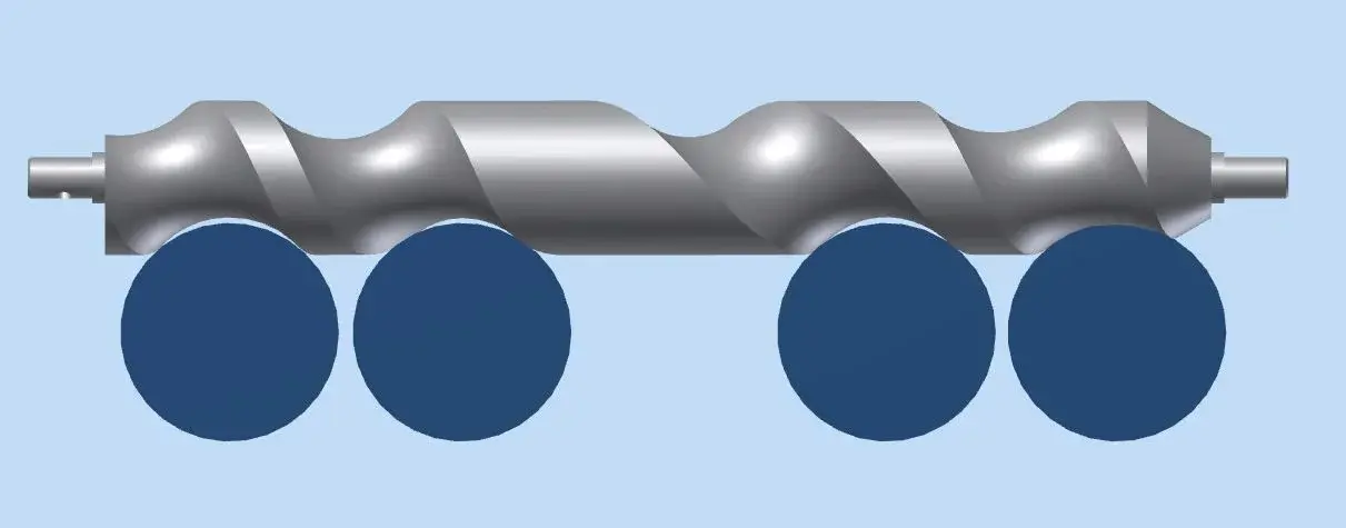
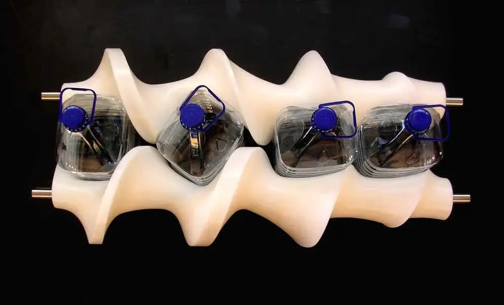
problem : I have to build a cochlear with 4 linear steps the first 2 the step is 86.5 the third is173 the fourth 86.5, this to move a jar ø 85 (premix that you can build well with a cnc machining).
My bran is : you can model such a cochlea in inventor 2k11 faithfully.
I attach 2 images to make it clear and the 2 ipts; the coclea 1 is made with the method described in the forum and is the most faithful (but with the problem that in step 173 the jar is in collision with the 2 sides of the trapezoidal profile), while the second was made with a sweep subtraction created with an envelope line around my cylinder.
(I have read the previous discussions but none of the discussions I have read has been decisive in my opinion )

Sorry I wasn't very clear. Hi.
 

Attachments

  • Coclea 1.webp
    Coclea 1.webp
    26.3 KB · Views: 66
  • Coclea 2.webp
    Coclea 2.webp
    13.7 KB · Views: 60
  • Coclee.zip
    Coclee.zip
    2.3 MB · Views: 79
the suggested methods to the forum still have not tested them (they look interesting) but if I need propellers with variable step use this method:
in a 3d sketch I create many helical curves one behind the other with the step and the revolutions I need. I use the constraints to bind the axis of each helid and then bind the ends of the curves between them.

place files as an example
 

Attachments

just diegus but...
I have always done them as you say with the helid, but in the specific case where the coclea has to move a cylindrical body that must remain perpendicular to the axis) , the profile (which you see from the view from the top ) that advances the jar must be constant . if you see from the images attached the ø of the jar hung on the sides of the pitch + long because radially it is + small.
in the cnc processing the tool of ø 85( perpendicular to the axis of the axis of the axis of the axis of the axis while it turns with the ratio 1 turn > 86.5 mm step and 1 turn > 173 mm step this determines that the resulting location (view in plant ) is constant . I hope to be explained
 
This discussion was born a few years ago from a post, it seems like vigz, and there was also evidence of the non-fidelity of a sweeping profile.
Anyway, I think your problem is that you can't replicate what happens in reality with the cnc.
in fact inventor makes you an elliptical excavation; But then, (I didn't try and maybe say a caxxata) why not use an ellipse instead of the circle... how to do this ellipse? Maybe projecting on a plane the excavation that sweeps, measures in what percentage you "stringe" the circle, and act accordingly opposite on the sketch of the sweep profile...
 
It's not even an ellipse but a more complex figure, so it would be difficult to create an exact ad hoc profile.
rather two questions:
- the tool you use is a cylindrical cutter of ø 85 and longer than the diameter of the cochlea?
Can you summarize, maybe with an example, what came out about during the Modena forum?
 
I try to explain.
in attached files there is coclea_2.ipt. see how it was created ? it starts with a cylindrical profiling that is explained , on the created parallelepiped they are carried out sweeps that are nothing but the grooves of the step.( at the forum they created a classical augmentation and made a sweep of the tooth , but it is the same thing ) then it is folded and the game is done.
the substantial difference is the way to build it. What I want is built with a cylindrical cutter working on the side of the screw (I said ø 85 but it can be ø16 working on interpolation) while the normal screws are turned, or welded and can be obtained with a helid.
 
I try to explain.
....................................................................................................................................................................................................................................................................................................................................................................................................................................................................................... .
working for interpolation with the coclea that turns on the swivel head with the step you said before and doing more past, or working for interpolation but on exact mathematicians?
 
if you have the cutter ø = seat you will advance the cutter of the step x turn if instead you have the cut + small so many passes to get the desired profile .
Hi.
 
It is sure that they are exact maths.

see photo attached
 

Attachments

  • Rotatore-8lt-1.webp
    Rotatore-8lt-1.webp
    36.2 KB · Views: 77
No. It was just to make it clear that the profiles have to be exact, then you can do almost anything you want.
 
I subscribe in full lui_verde ... apparently it is not possible to generate to inventor sweep generated by solids.

I searched online and here on the forum but it seems to be an intrinsic problem of inventor.

I would also like to be able to shape my axles without having to rely on our trusted manufacturer, and I have the same problem in generating a twist that roars around a board my tablets.... Does anyone have any workarounds?
 

Forum statistics

Threads
44,997
Messages
339,767
Members
4
Latest member
ibt

Members online

No members online now.
Back
Top