vale79
Guest
Hello dear
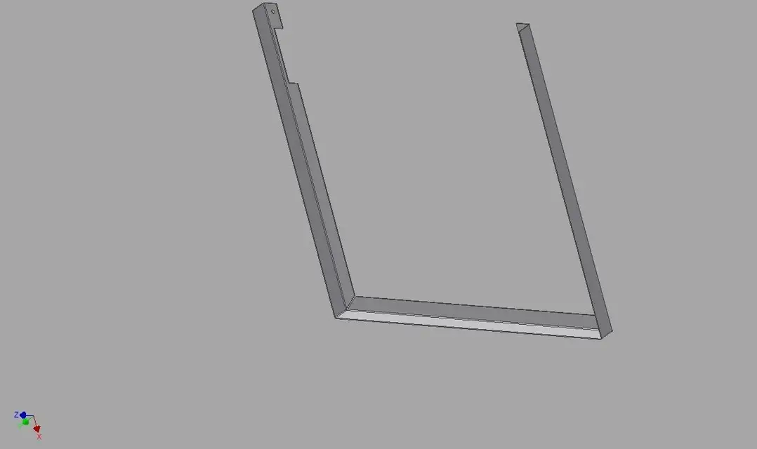
I'd need some advice, please. I designed this piece with the sheet module, but I think I didn't use the right procedure. Can someone explain to me how it should be done properly?
Thank you very much
Hi.
That's right.
I'd need some advice, please. I designed this piece with the sheet module, but I think I didn't use the right procedure. Can someone explain to me how it should be done properly?
Thank you very much
Hi.
That's right.
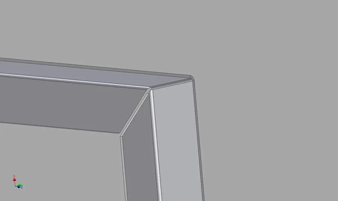
 ok... thank you very much, I understood the concept and you confirmed what I suspected... at the end the piece vaguely resembles the result I should have, but it is not the right procedure for inventor, for this then it does not develop and the sides do not remain parallel.
")
