
You are using an out of date browser. It may not display this or other websites correctly.
You should upgrade or use an alternative browser.
You should upgrade or use an alternative browser.


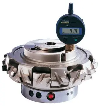
SolidUser
Guest
follow the construction procedure that takes place in reality.
How would they do that?
with work.
then extrude a cylinder and work with sweeps and circular sweep repetitions.
How would they do that?
with work.
then extrude a cylinder and work with sweeps and circular sweep repetitions.
malpella
Guest
it is true what you say but if one does not know how to use sw it is a little difficultfollow the construction procedure that takes place in reality.
How would they do that?
with work.
then extrude a cylinder and work with sweeps and circular sweep repetitions.
Anyway I managed to do this
but the gorges are radiated but straight instead in the photo are tilted 30 ° but propio can not help her? ?
Attachments

marcof
Guest
If I have understood well what are the gorges you need inclined, cut with sweep using a helical angle path of 30° and as a profile the section of the throat.it is true what you say but if one does not know how to use sw it is a little difficult
Anyway I managed to do this
but the gorges are radiated but straight instead in the photo are tilted 30 ° but propio can not help her? ?
all you can do then as circular repetitions, possibly guided by the sketch so you can use those functions to automatically repeat the components in the axieme (knives, shaves, lards, grains etc.)
malpella
Guest
in the propeller function I do not find how to give the inclination 30°If I have understood well what are the gorges you need inclined, cut with sweep using a helical angle path of 30° and as a profile the section of the throat.
all you can do then as circular repetitions, possibly guided by the sketch so you can use those functions to automatically repeat the components in the axieme (knives, shaves, lards, grains etc.)
Sorry.
malpella
Guest
marcof
Guest
set the propeller by step and revolution or by step and height then the step to set the revenues by calculating it from the angle (30°) of the desired propeller: step=pigreco*d*tan30 where d is the diameter of the circle from which the propeller revenuesin the propeller function I do not find how to give the inclination 30°
Sorry.
marcof
Guest
I opened it up. I'm in a hurry, but I saw you have a lot of geometry in the underdefinite sketches. If it's for a flight test you've done, it might even be there, otherwise that model is a wandering mine. depart from the first feature and bind everything well.I attach the design I tried to make I accept advice and criticism
Thank you.
malpella
Guest
can you give me some advice or even better to fix it even calmly so that you understand well?I opened it up. I'm in a hurry, but I saw you have a lot of geometry in the underdefinite sketches. If it's for a flight test you've done, it might even be there, otherwise that model is a wandering mine. depart from the first feature and bind everything well.
Mike1967
Guest
the best way is to get there and see "why" is subdefinitionOnce you understand, you automatically get out of the sketch only when all entities are black.can you give me some advice or even better to fix it even calmly so that you understand well?
to make you understand: sketch2 : add equality report (=) to segments
that start from the origin, once you do that you will have only the 15 mm sement
to which you will have to add a quota (60) to make the sketch totally defined.
read the topic I posted to you, it's the basis for not having big problems
as the piece gets complicated. :finger:
in doing these operations I highly recommend you to drag the Insert barup to the first processing.
by hand the transfer to the next processing.
repeat procedures for subsequent sketches you used for ,sweep, sweep cuts etc.
marcof
Guest
If you fix it, someone and you reopen it doesn't learn a pipe and you can't figure out what was done. do as mike told you and make all the sketches completely defined.can you give me some advice or even better to fix it even calmly so that you understand well?
then for cutting along the helid we see, in the meantime you can do tests on any cylinder to hang you and understand how to guide everything.
malpella
Guest
I can make all the sketches defined except the 19th block me sw how come? ?the best way is to get there and see "why" is subdefinitionOnce you understand, you automatically get out of the sketch only when all entities are black.
to make you understand: sketch2 : add equality report (=) to segments
that start from the origin, once you do that you will have only the 15 mm sement
to which you will have to add a quota (60) to make the sketch totally defined.
read the topic I posted to you, it's the basis for not having big problems
as the piece gets complicated. :finger:
in doing these operations I highly recommend you to drag the Insert barup to the first processing.
by hand the transfer to the next processing.
repeat procedures for subsequent sketches you used for ,sweep, sweep cuts etc.
malpella
Guest
I understand what you're saying, but if someone like you does it, I'd understand how to build my tools.If you fix it, someone and you reopen it doesn't learn a pipe and you can't figure out what was done. do as mike told you and make all the sketches completely defined.
then for cutting along the helid we see, in the meantime you can do tests on any cylinder to hang you and understand how to guide everything.
For example, I used a method of cabbage, creating a bevel on the face, you will have noticed that there are things wrong, we say to the "carlonna" but only because I found no other way.
I attach the modified drawing except sketch 19
Attachments
marcof
Guest
That is a hallucinating sketch: eek: I made the automatic definition because I didn't intend to go crazy to define it as you did it and it took almost two minutes but eventually defined it. see image imageI can make all the sketches defined except the 19th block me sw how come? ?
imho you can't really shape that way. You have to do simple sketches and make sense for what you have to build after. you could make a clove looks like 1/5 of the cutter (has 5 cutting edges, 5 drains etc) with all or almost processing then make a single circular repetition.
It's hard to advise you because you know how the tool has to be done. thinking in terms of traditional mechanical processing can also go well but you do not have to overdo it. you have to take advantage of the characteristics of the cad that allow you to reduce the work by repeating, mirroring, sharing etc. do not make one for every step you do in the workshop.. .
Attachments

marcof
Guest
I understand what you're saying, but it's gonna take so much time to get that frickin' back.I understand what you're saying, but if someone like you does it, I'd understand how to build my tools.

make a plan on the vertical edge, draw the profile of the material to be removed and make a cut "to the surface by selecting the arrival surface.For example, I used a method of cabbage, creating a bevel on the face to do the tilted inserts at 30°.
I had a good buzz to try to figure something out, but with all those sketches shared at this time I don't regret. you have of those unnecessarily complex that you would have solved with four lines in crodes and two or three quotas (see sketch 9).
I had to do that brake I would start from scratch trying to figure out what the geometry groups are to repeat circularly, how to simplify the sketches and above all I would realize that then some geometry must be realized on a tool machine so it may not be the case of making cuts "to the surface" like what I told you above, because then if you do it with a candle mill on the bottom you have a plane and not a cylindrical surface.
I mean, you're the one who builds them and you need to know what type of 3d model you need.
If you leave from zero and away you expose the difficulties you can perhaps give a hand. put in order such a model thinking of having to completely remake the features from the beginning both as sketch and as type of real feature is a delirium, or at least I in the short time that I can dedicate to these things I can not.
malpella
Guest
I did as you told me to start overThat is a hallucinating sketch: eek: I made the automatic definition because I didn't intend to go crazy to define it as you did it and it took almost two minutes but eventually defined it. see image image
imho you can't really shape that way. You have to do simple sketches and make sense for what you have to build after. you could make a clove looks like 1/5 of the cutter (has 5 cutting edges, 5 drains etc) with all or almost processing then make a single circular repetition.
It's hard to advise you because you know how the tool has to be done. thinking in terms of traditional mechanical processing can also go well but you do not have to overdo it. you have to take advantage of the characteristics of the cad that allow you to reduce the work by repeating, mirroring, sharing etc. do not make one for every step you do in the workshop.. .
I attach the new file, now I have only worked on a clove but with extrusion 6-9 (if I don't remember bad) it doesn't make me do the circular repetition
p.s. for reasons of the customer are not + 5 ears but 8
wait for your advice
Attachments
Mike1967
Guest
... and there is reason: you can't repeat cuts if there's nothing to cut!I did as you told me to start over
I attach the new file, now I only worked on a snitch but with extrusion 6-9 (if I don't remember badly) doesn't make me repeat circularp.s. for reasons of the customer are not + 5 ears but 8
wait for your advice
marcof
Guest
because as Mike said, he finds nothing. . .I did as you told me to start over
I attach the new file, now I have only worked on a clove but with extrusion 6-9 (if I don't remember bad) it doesn't make me do the circular repetition
I tried to change the least essential model, but it's still a mess with sketches and see it later.
I attach a file avi that should clarify what I mean to exploit the possibility of repetitions
for how you destroyed that frieze, especially in the first version, making that change would become a mess. you will see in the video that I simply connected the number of feature repetitions with the angular value of the cutting edge. change that and rebuild the frieze.p.s. for reasons of the customer are not + 5 ears but 8
I have not touched almost indent of your model (if we want to quote bartali: "It's all to do :redface
 except for the first feature I made by changing the first sketch by adding the line that defines the "brake" and little more after you can see comparing yours with my video.
said this the quotation to bind the sketches is almost always chilling because you used the automatic quotation and because I have the shame that starts drawing a lot "to the eye".
Besides in the first sketch you have a line that you have stuck with a "fix" and this is bad, terrible:bekle:; If you want to be bound, use the constraints and quotas.
then, the cuts you make by extruding along the direction do not need every time of a new sketch that contains the line: you do one and click each time on that the cut takes the right direction even if it is in a position different from the tilted line then you can delete the shizzi 6 and 11
the profiles you use to make the cuts at 30 ° are on a floor that is not perpendicular to the cutting direction, which is then the direction that must make the tool to do that processing; It goes without saying that geometries don't think they're the ones you thought when you drew the profiles. for straight itagli make first a reference line tilted to 30°, wider than the body of the cutter. in the center create a perpendicular plan. on that design the profiles (scaric, knife seat etc) and make extruded cuts along the direction by selecting medium plane or other methods to define the depth of the cuts.
plan_2 does not serve because it is on the face of the body of the cutter: You use that as a sketch plan, right?
try and let us know
Attachments
Mike1967
Guest
quoto marco. :wink:
I, malpella, put you this video (that... is called as the one posted by
marco lol...) where you can see how to save goats and cabbages with what you have already created in two simple clicks.
I don't add anything else, marco has been precise enough, but look at it also just to understand the possibilities that the software offers you.
http://www.mediafire.com/?eel3zl5r2hptlbg
I, malpella, put you this video (that... is called as the one posted by
marco lol...) where you can see how to save goats and cabbages with what you have already created in two simple clicks.
I don't add anything else, marco has been precise enough, but look at it also just to understand the possibilities that the software offers you.
http://www.mediafire.com/?eel3zl5r2hptlbg
malpella
Guest
thanks to your help but I'm stepping in a month maybe I'm done (I'm a little hard on my head maybe) but I don't have so much time, the customer would kill me, better than I let them keep doing them out like I did until now.
sorry x loss of time
sorry x loss of time