
• This forum is the machine-generated translation of www.cad3d.it/forum1 - the Italian design community. Several terms are not translated correctly.

sform of a printed piece

  • Thread starter Thread starter _JayD_
  • Start date Start date

_JayD_

Guest
Hi guys, I just signed up and I already need you:d
I should draw this piece
if you notice, at the center of the fork is formed a sform angle that creates a division of the surface in other 4 convergent surfaces (this I saw it at the design of the prof in which the mesh was shown)
How do you do it? ?

Thank you.
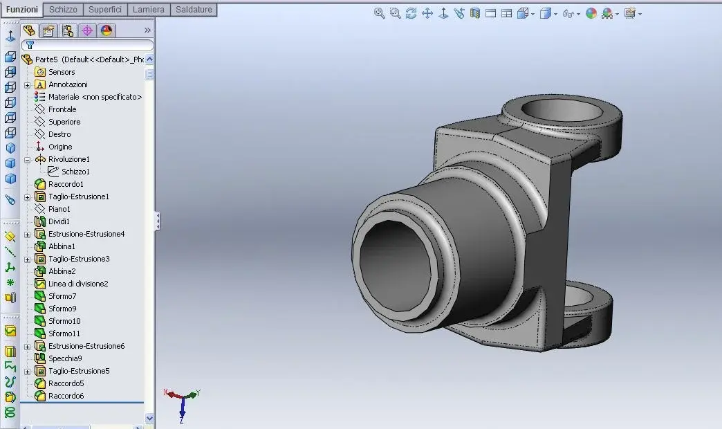
 
Hello, are the 4 surfaces listed in the annex or what?
 

Attachments

  • sformo.webp
    sformo.webp
    41.9 KB · Views: 27
thank you for the answer first;)
I don't know if it's clearer now, let's say I've tried to do manual mesh.
 
thank you for the answer first;)
I don't know if it's clearer now, let's say I've tried to do manual mesh.
the 1st image does not show the facets that you show after,
In the first case I would use the sforma command that you find in the extruded command,
If instead you have to add facets, I would create new plans and cut the material....

but surely others will know to be more "professional" than me:tongue:
 

Attachments

  • forcella.zip
    forcella.zip
    266.1 KB · Views: 9
  • sforma1.webp
    sforma1.webp
    79.3 KB · Views: 19
Hi.
I think it's an aesthetic fact.
get a series of unformed facets
In fact, if the fork is obtained from fusion
the deform must or at least it was until recently "radial"
both external and internal
Thank you very much
 
the problem is that the prof showed it very quickly as he did using a plan passing from the center of the fork. The problem is I don't remember how.
He definitely didn't use any other plan or anything.
I remember that it was a function in solidwoks that just give it the sform angle and the neutral plane, the rest calculated it alone the program... but I can't:d
 
the problem is that the prof showed it very quickly as he did using a plan passing from the center of the fork. The problem is I don't remember how.
He definitely didn't use any other plan or anything.
I remember that it was a function in solidwoks that just give it the sform angle and the neutral plane, the rest calculated it alone the program... but I can't:d
hi jay, keep in mind that swx always has 10 different ways to reach a goal, from time to time you should have the experience to understand in advance which road will give you less problems with subsequent work and this is not always easy and immediate. . .

That said, I think the result is important and not the way you took so I wouldn't worry so much.. .

Finally, I understand that you are a student and the teacher is a teacher/teacher, the most beautiful thing would be that you would ask him, without fear, to show you again the technique he used and that he wanted to teach you/you, in this way you will both perfectly do his job.

... then if you teach us too, we can learn something too:

Let us know
 
hi jay, keep in mind that swx always has 10 different ways to reach a goal, from time to time you should have the experience to understand in advance which road will give you less problems with subsequent work and this is not always easy and immediate. . .

That said, I think the result is important and not the way you took so I wouldn't worry so much.. .

Finally, I understand that you are a student and the teacher is a teacher/teacher, the most beautiful thing would be that you would ask him, without fear, to show you again the technique he used and that he wanted to teach you/you, in this way you will both perfectly do his job.

... then if you teach us too, we can learn something too:

Let us know
You're right, but I'm a university student and I see him once a week......... on Friday, the day I have to deliver the drawing:(
In cases such as this, it is difficult that there are ten roads because there are very precise rules to carry out that type of sform and varies according to the geometry of the piece............the function of solidworks is to calculate him as it should be done:d I can not tilt plans at home:wink:
 
... on Friday
Ahi...

try to see the attached image, search sforma and look for help with f1...
But I feel that it is difficult for solidworks to calculate him as your piece should be done. . .
 

Attachments

  • sforma2.webp
    sforma2.webp
    55.3 KB · Views: 12
with the sforma command, it is ideal but what I can't do is: once you choose the neutral plan, to sform in both directions than it..................instead I can't do it
 
with the sforma command, it is ideal but what I can't do is: once you choose the neutral plan, to sform in both directions than it..................instead I can't do it
I tried both with the sforma command (I gave him 7 degrees) and with the extruded cut command (rebalting the side to cut)
to use the sforma command I created a division line (see image 1) on the face and then I used the sforma command from division line (image 2)
image 3 refers to the second method, i.e. from extruded cutting
obviously with the cut command extruded the division line on the face does not need.

and image 4 is the finished piece

Surely there are other methods (using also surface controls) but I think that one of the 2 solutions I have proposed is the fastest method.

If you have any questions ask :finger:
 

Attachments

  • immagine1.webp
    immagine1.webp
    52.7 KB · Views: 16
  • immagine2.webp
    immagine2.webp
    52.4 KB · Views: 16
  • immagine2bis.webp
    immagine2bis.webp
    54.3 KB · Views: 15
  • immagine3.webp
    immagine3.webp
    58 KB · Views: 19

Forum statistics

Threads
44,997
Messages
339,767
Members
4
Latest member
ibt

Members online

No members online now.
Back
Top