• This forum is the machine-generated translation of www.cad3d.it/forum1 - the Italian design community. Several terms are not translated correctly.

pin sizing

  • Thread starter Thread starter Merka73
  • Start date Start date

Merka73

Guest
Good evening to all

I need to size a pin and I'm losing myself in a glass of water.
I ask help to those who are cooler with calculations and know more about me.
In practice they are insecure on the free body diagram for the pin.
determined this, we proceed with the specific bending, cutting and pressure verification.

problem data:
1) on the wheels we have a ground reaction of 45000n in point a.
2) the cylinder (not represented) pushes with a force of 30787n inclined by 40° regarding the ground in point b.
3) the structure is free to rotate around the point c that remains fixed.

I think that pin won't resist, but I have to prove it with the numbers.

Thank you in advance.
 

Attachments

I try to post a pattern but you don't understand where the force is. how to mix the angle and clockwise/anticlockwise. post the right pattern.

then it's like solving a trave cart / isostatic hinge where you have the strength of the cylinder fcil and the reactions I have marked you rcx, rcy. at the point d i.e. of the pin you will need to see how internal actions act and then transfer everything to the pin section.

then the reaction in a is that or is it half for each single wheel? (I think it should be divided by 2 but then it correctly considers the set and therefore will remain equal, that is the total one).

However the force turns, keep in mind the same pattern. someone will have calculated the reactions and hope they are right.

for verification you can use the classic method with von mises and specific pressure, but I suggest you use the eurocode 3 which ultimately has the parameters for pins and limit values restrictions.

I'll make you think.

after you have settled and clarified scheme and if the force is that or half or double you will know how to move forward because the reasoning is that attached.
 

Attachments

very quickly:
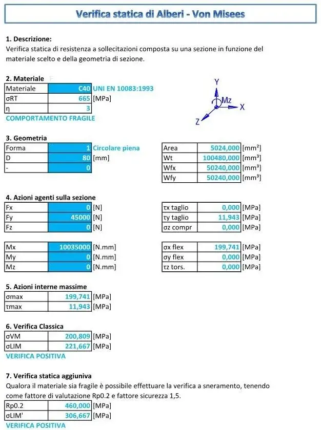
= 10035000 n*mm
y = 45,000 n
static verification with c40e in the rectum state (it should be tempered) with the method of the sigma of von mises compared with rm/3 you have a Insufficient ø45.
without carvings at least ø80. lacks pressure verification and possible fatigue verification.

Still the design pin, with those forces you gave us does not resist. unless that pin is studied to yield him before the whole structure breaks. See Annex.
ps: I recommend you check the reactions of that cart, because I have some doubt that ra is so high.
 

Attachments

  • VP_1.webp
    VP_1.webp
    57.4 KB · Views: 186
thanks for the collaboration.
I take a step back to explain the problem in its entirety.
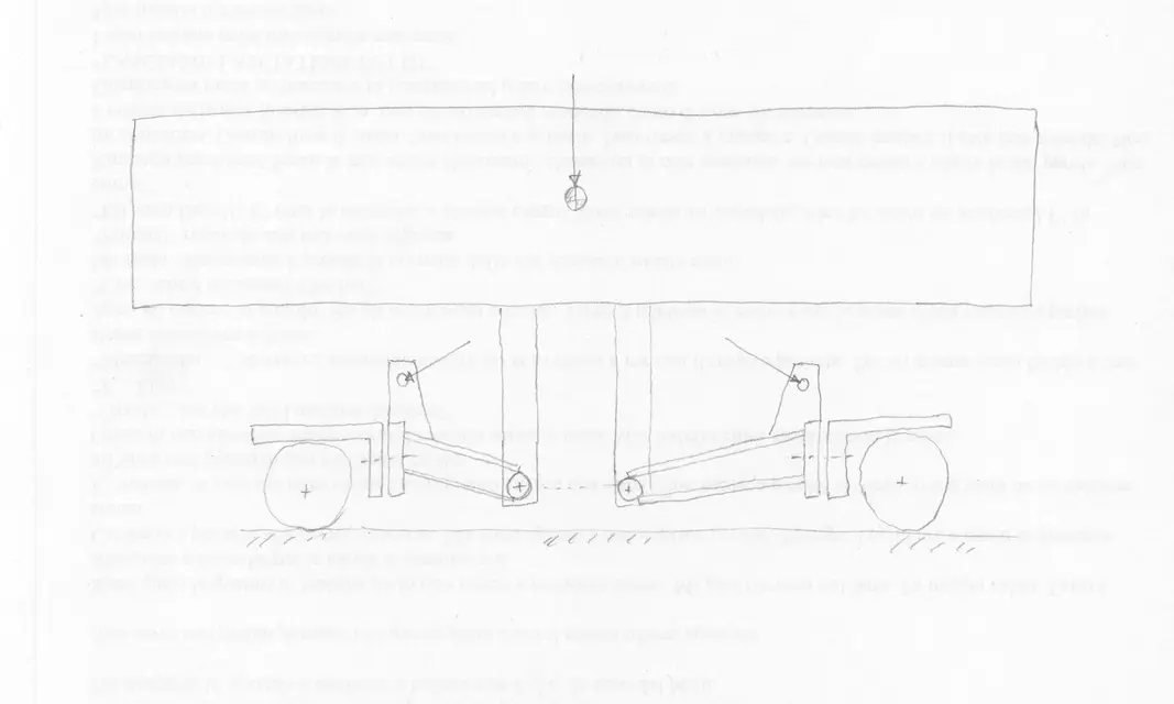
we have a symmetric machine with a mass of 7000kg which is lifted with 2 identical axles (the design sucks but makes the idea).
the real problem is the choice of the cylinder and the diameter of the pin.
They told me to put a cylinder with alesage of 70mm and p=80bar and a pin with diameter=45mm.
I want to show that the choices are wrong and propose the optimal solution.

actually ra=(3500kg)*g=34335n because the machine is symmetrical.
to take into account holes it is considered ra=(4500kg)*g=44145n rolled to ra=45000n
the images are with the machine all lifted where I have the max efforts.

The pattern you made is right.
I didn't understand the Eurocode method? ? ?
I make 2 accounts and the place

Thanks again.
 

Attachments

  • intera macchina.webp
    intera macchina.webp
    155.1 KB · Views: 140
Well, then my imagination led me to just interpret the system. Are you sure that the maximum effort is raised and not in condition as you schematized?

for eurocode 3 there is all the sizing and verification of replaceable pins, with all formulas and all coefficients to be considered. It would be worth it to remain sufficiently careful. what the norm does not rewrite is the fatigue test that at this point seems to me to be due and evaluated with particular attention.
 
the configuration in the drawings is what I call to machine lifted and that is when walking on the road.
in the rest configuration, those supports for the wheels are lifted because of the cylinders and the machine is rested on fixed supports not represented in the drawings and solids on the ground.
 
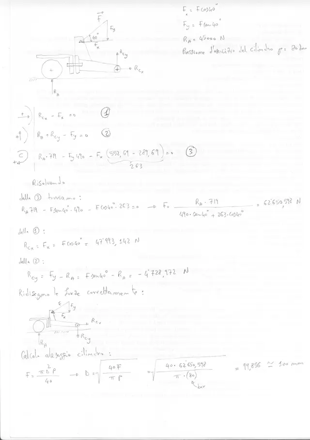
here is the free body diagram for the front lifting system.
share my thoughts?

now I try to make the other diagrams
 

Attachments

  • FBD assale anteriore.webp
    FBD assale anteriore.webp
    185.9 KB · Views: 155
Mechanical

the spreadsheet you posted is commercial or are you prepared because you carry similar calculations daily?

Thank you.
 
Mechanical

the spreadsheet you posted is commercial or are you prepared because you carry similar calculations daily?

Thank you.
the excel sheet of the internal actions I did it a few years ago, it is not commercial nor commercial :biggrin:

It is a simple atuomation of the usual calculations in the stress section.
 
here is the free body diagram for the front lifting system.
share my thoughts?

now I try to make the other diagrams
until here I agree, even if for the size of the cylinder should be chosen a higher size because of the frictions, all in all will increase slightly the time lifting but by static way 100 mm of alege guarantee to 80 bar 6265 kg thrust.
 
As for the cylinder, 2 cylinders of diam=70mm will most likely be placed in parallel.

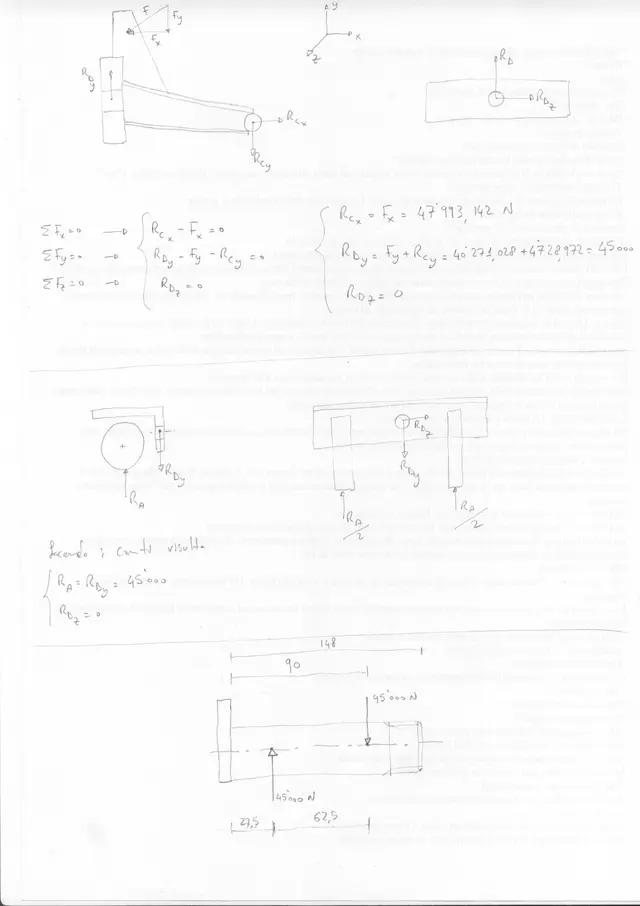
Here are the other diagrams.
the pin behaves like a beam simply supported and subject to 2 equal and opposite forces.
I can't find the mf moment you used.
 
As for the cylinder, 2 cylinders of diam=70mm will most likely be placed in parallel.

Here are the other diagrams.
the pin behaves like a beam simply supported and subject to 2 equal and opposite forces.
I can't find the mf moment you used.
if you break besides rdy you also have a moment and definitely also a normal action. the pin makes from sleeve + normal action = ink even if it rotates in the other way. So you have m, t, n. then you balance.

I simply took rya * distance to center pin, this is the time I used for calculation, since all axis is like a unique beam taken as first approximation.

As you rightly broke, you have to balance.
 
Your reasoning comes back and is correct.
I'm the one who was wrong to schematize the pin's bond.

bye
 
very quickly:without carvings at least ø80. lacks pressure verification and possible fatigue verification.
In fact, I would recommend not to settle for a static stress sizing, lately I see of those fatigued breaks to impress.
actually ra=(3500kg)*g=34335n because the machine is symmetrical. to take into account holes it is considered ra=(4500kg)*g=44145n rolled to ra=45000n
Here is the holes, I would also add the impulses provided by the cylinders during attack/stack. I would not underestimate them, sometimes you can reach peaks with values not easily imaginable and to follow damages that accumulating over time... Well, you know that.

so to feeling I see badly that head in the pin (the shoulder).
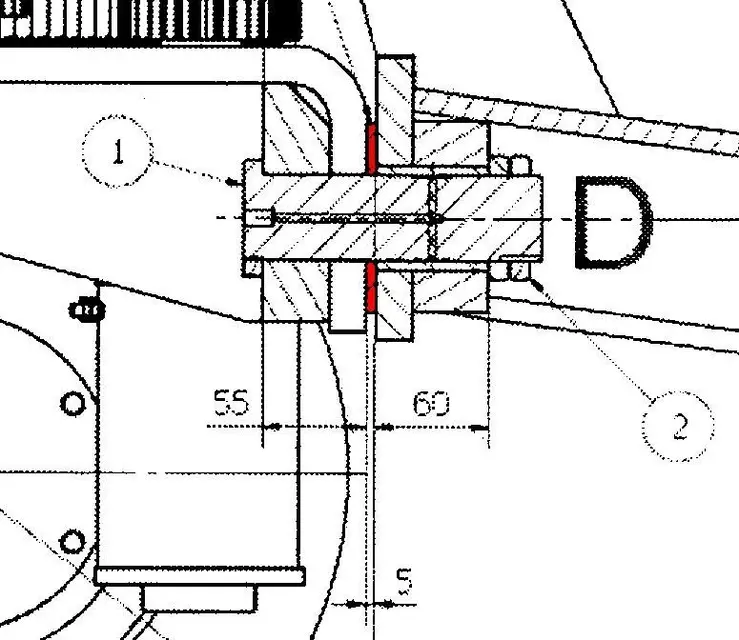
Moreover, in the drafting of the diagram of the forces I would consider the actions reactions on the distantial basis that I have highlighted in red. Of course the larger the base is the load exerted on the pin due at the moment.
 

Attachments

  • Mozzo1.webp
    Mozzo1.webp
    68.8 KB · Views: 50
I would also evaluate very much but very much the fact of replacing the fine-step wreath with a large-step nut with a perforated cap and a couple. it is very good that you do not tear the fillet under load.
 
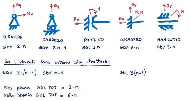
for completeness I attach a scheme of constraints used in structures, as a reminder for anyone who needed it.

I have indicated with n the number of auctions, with gdv the number of bond degrees blocked by the constraints themselves, with gdl the number of degrees of freedom of structures.

all is for the case of bond on the ground, and of internal bond.
 

Attachments

  • vincoli.webp
    vincoli.webp
    31 KB · Views: 73
the spacer in red is made of teflon (or other antifriction material) and has dint=46; dest=100; thickness=5mm.

the pin is schematizable as a supported beam. the 2 supports are at the centre of the supporting surfaces, i.e. half of 55 and 60.
I find the usual strength of 45000n (in opposite verses) in the supports but 2 different moments as verse (and I return) and module (not confince the result).
rdx=0.
as soon as I can place the diagrams
 
the spacer in red is made of teflon (or other antifriction material) and has dint=46; dest=100; thickness=5mm.

the pin is schematizable as a supported beam. the 2 supports are at the centre of the supporting surfaces, i.e. half of 55 and 60.
I find the usual strength of 45000n (in opposite verses) in the supports but 2 different moments as verse (and I return) and module (not confince the result).
rdx=0.
as soon as I can place the diagrams
We wait to scan the formulas. Then let's see what doesn't work.
 
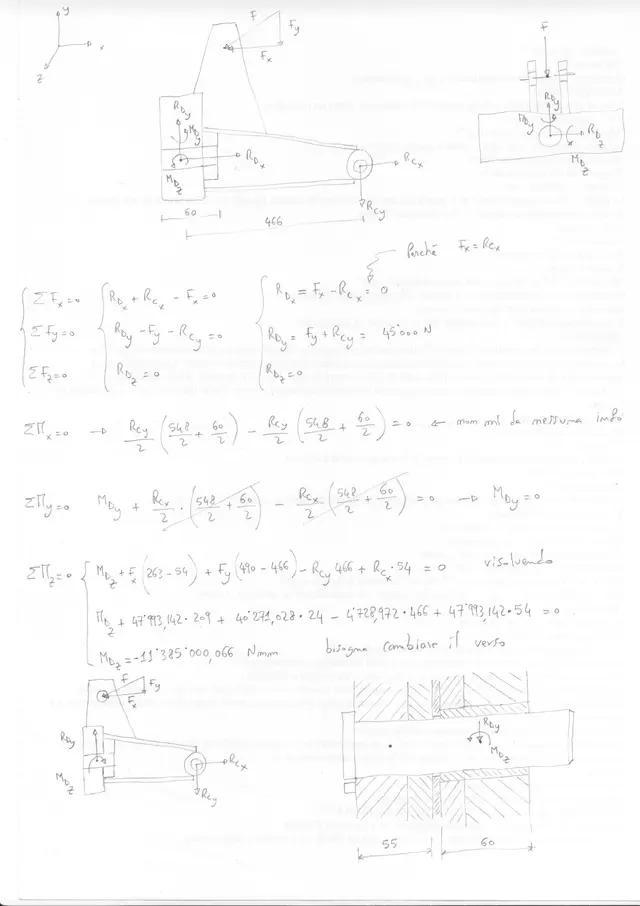
Meanwhile I attach the diagrams related to the support.
I hypothesized the internal constraint pin+ghiere as a bond that prevents x, y, z and rotations from y, z axes.
fx, fy, rcx, rcy values derive from the free body diagram for the whole system.
Do you agree with the setting?
the rest the place tomorrow (the eyelids see me hour)

Thank you.
 

Attachments

  • FBD supporto.webp
    FBD supporto.webp
    219.6 KB · Views: 60

Forum statistics

Threads
44,997
Messages
339,767
Members
4
Latest member
ibt

Members online

No members online now.
Back
Top