• This forum is the machine-generated translation of www.cad3d.it/forum1 - the Italian design community. Several terms are not translated correctly.

cleaning one superficie

  • Thread starter Thread starter arzigogolo
  • Start date Start date
... "a cad" the holes should be made after the curvature (at least those on the curved part, on the flat face is indifferent) with the option normal cut" active (otherwise, as mentioned, the upper holes will be deformed and not concentric to the lower ones). in this way the program in development will recognize the form "ovalized" allowing to create the correct 2d to send to laser cutting.
in the "real construction" the shape of sheet metal will already be ready and perforated by the laser (or other methods..) according to the 2d above... of course the bending process must be accurate to respect concentricity.

greetings
Mar
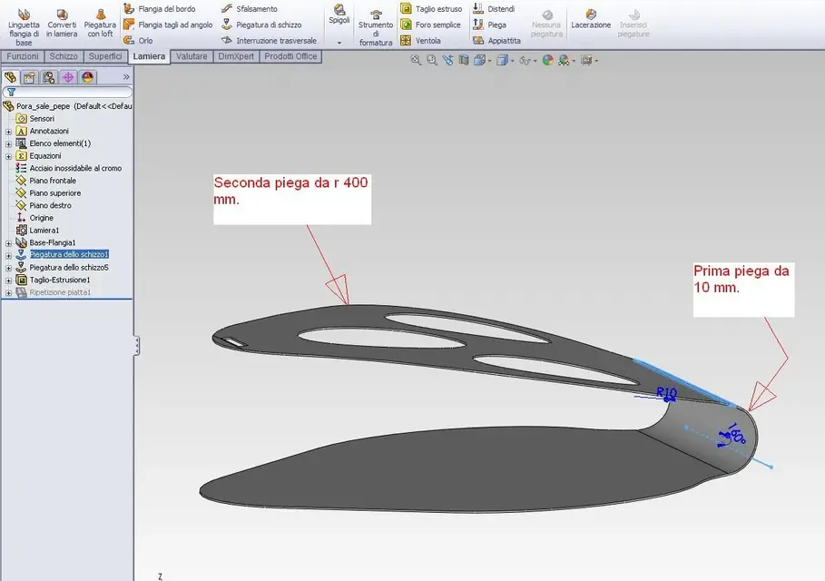
 
hi arzi thanks you more or less are those the landscapes

How come you made two folds one by 10 in which area??? And a 400? ?
that of 10 mm is the fold in the half-work of the piece as seen in the attached image, while that of radius 400 mm is the fold that gives the curvature to the upper flap (where there are the holes that ovalize to understand us).portasale_pieghe.webp
in one shot couldn't you???, or for your own personal need? ? ?


Hi.

thanks rs4
No, it is not for a particular need, it is because it is the first method that came to mind.
in a single shot I would have probably managed to start modeling the part in another way as suggested by re_solidworks and that is, starting from the side profile of the piece and then giving it the depth with the command "baseflangia" and finally shaping the model with the other processing until it confers its final appearance.
then I could have done everything in one shot and as soon as I can try to do it as well to see how it comes.

Hello, thank you.:smile:
 
not to break the boxes, but according to me the round cuts for the containers of salt and pepper were made last. If you do them first and then pierce them the jar no longer enters with uniform play.
... "a cad" the holes should be made after the curvature (at least those on the curved part, on the flat face is indifferent) with the option normal cut" active (otherwise, as mentioned, the upper holes will be deformed and not concentric to the lower ones). in this way the program in development will recognize the form "ovalized" allowing to create the correct 2d to send to laser cutting.
in the "real construction" the shape of sheet metal will already be ready and perforated by the laser (or other methods..) according to the 2d above... of course the bending process must be accurate to respect concentricity.

greetings
Mar
You're both right. in fact thinking about us better, if you make the holes before you realize the curvature, they will be ovalized because of the stretching and the jar of salt and pepper in the end will dance inside!:biggrin:

I didn't know this thing about the ovalized holes that should be made after the fold to allow the correct 2d recognition by the laser cutting machine as they are not very experienced in sheet metal processing.
I thank you again because you explained something I ignored and that I will definitely be useful in the work of mechanical designer!!! :finger::finger:

p.s.

and I didn't even know about this "normal cut" function, a great thing!
I think it's better that I do the tutorials on the sheet because there are so many things I don't know and inventor, it seems to me that this function doesn't have it.

Hello, thank you.:smile:

Light
 
and I didn't even know about this "normal cut" function, a great thing!
I think it's better that I do the tutorials on the sheet because there are so many things I don't know and inventor, it seems to me that this function doesn't have it.

Hello, thank you.:smile:

Light
I think it's weird that inventor doesn't have it.
is a fundamental function of all cads with sheet module.
pro/e always had it, think 3 has it, swx and if so.
 
p.s.

and I didn't even know about this "normal cut" function, a great thing!
I think it's better that I do the tutorials on the sheet because there are so many things I don't know and inventor, it seems to me that this function doesn't have it.

Hello, thank you.:smile:

Light
I think it's weird that inventor doesn't have it.
is a fundamental function of all cads with sheet module.
pro/e always had it, think 3 has it, swx and if so.
I also heard about this gap, but in my slow study/learning phase I'm still not arived at the inventor sheet. If it is missing it is a very serious gap because, in case of thick sheets, considerable errors are likely.
 
I think it's weird that inventor doesn't have it.
is a fundamental function of all cads with sheet module.
pro/e always had it, think 3 has it, swx and if so.
I also heard about this gap, but in my slow study/learning phase I'm still not arived at the inventor sheet. If it is missing it is a very serious gap because, in case of thick sheets, considerable errors are likely.
hello, king.

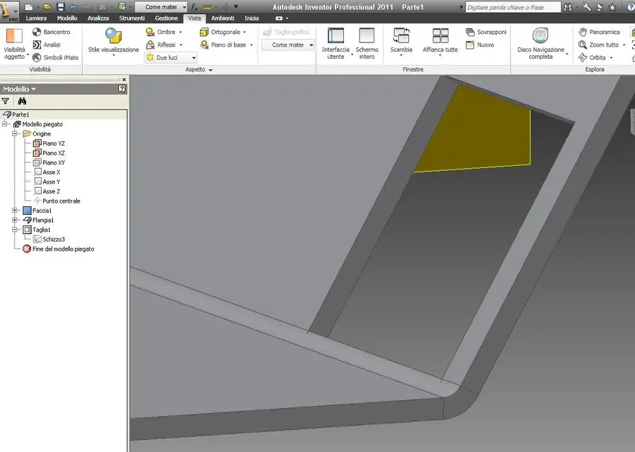
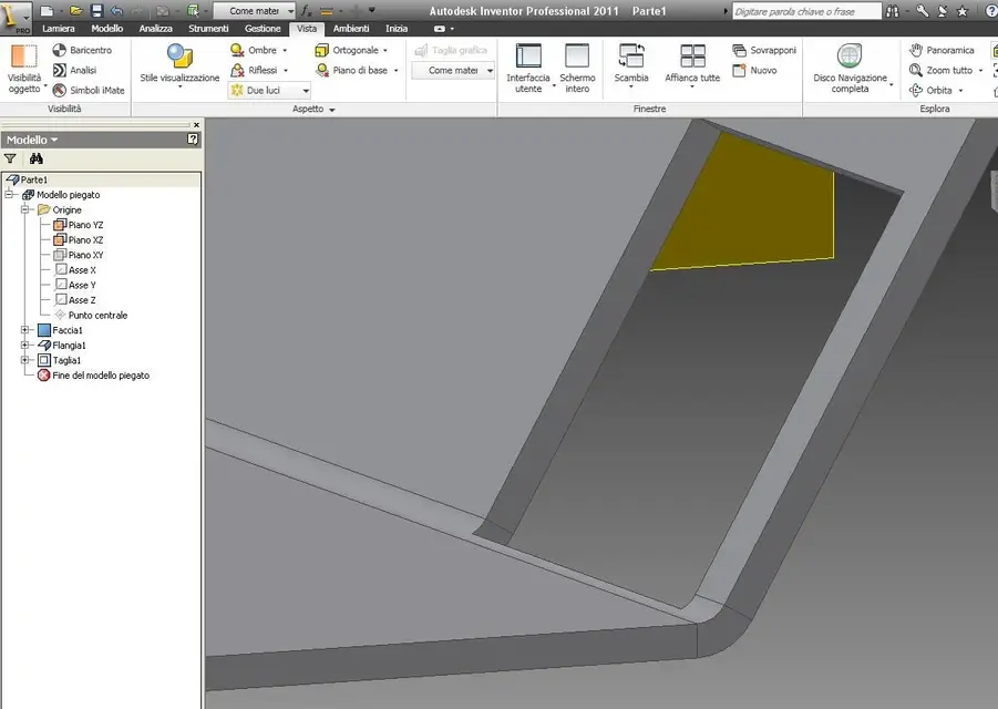
Yes, I remembered badly, the inventor function has it and is called "cut through fold" within the command "cut" for the plates. It is a casellin that goes "flaggata" and, depending on its activation or not, gives the result that can be seen in the two images.

in the profile that I used so much to make an example, I made the lower side of the rectangle coincide with the upper side of the bottom of the sheet, but depending on what you want to get, you can also make it coincide with the lower surface of the bottom of the sheet and, in that case, the result will differ slightly I think.

He does!
 

Attachments

  • taglio_attraverso_piega_attivo.webp
    taglio_attraverso_piega_attivo.webp
    53 KB · Views: 12
  • taglio_attraverso_piega_disattivo.webp
    taglio_attraverso_piega_disattivo.webp
    53.5 KB · Views: 10

Forum statistics

Threads
44,997
Messages
339,767
Members
4
Latest member
ibt

Members online

No members online now.
Back
Top