• This forum is the machine-generated translation of www.cad3d.it/forum1 - the Italian design community. Several terms are not translated correctly.

cutting edge

  • Thread starter Thread starter Paco
  • Start date Start date

Paco

Guest
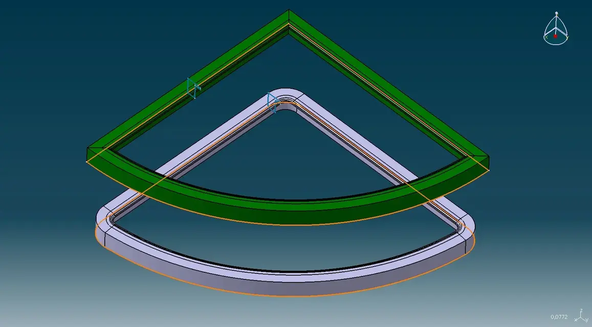
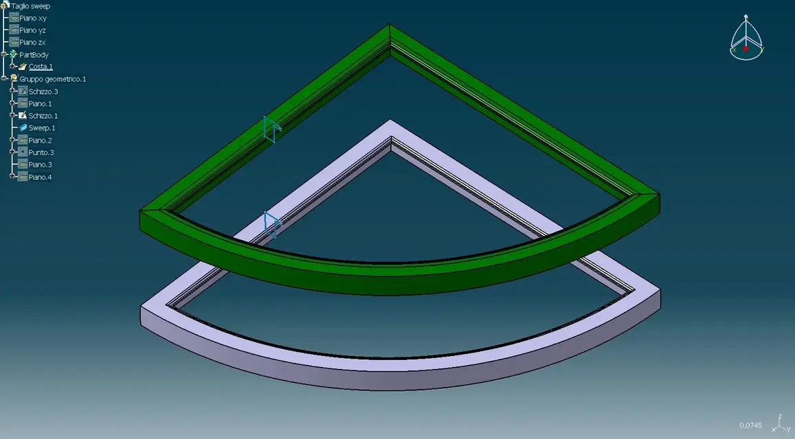
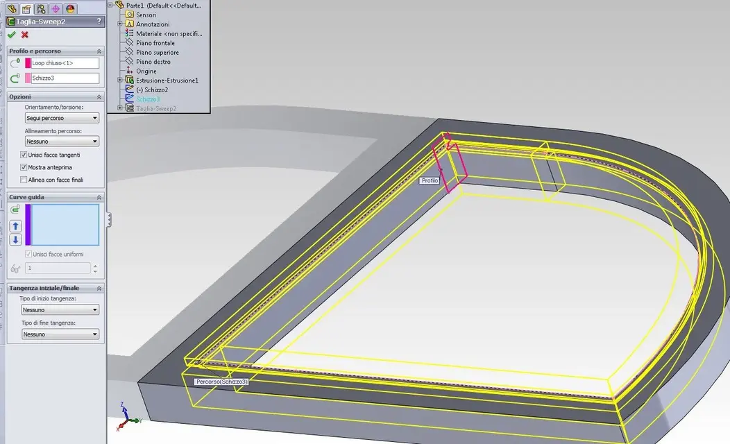
They asked me to make a rendering of a door... There's no problem I said, two minutes and it's done and I started to create profiles from the frames...drama. the sweep cut I thought was to the ideal function was insufficient. the curved parts in fact are not homogeneous at all and there are discontinuities of surfaces in addition to the fact that if I put on the table something like this does not give a ray of quotation as it turns out to be spline...where wrong?
 

Attachments

  • 2011-06-27_102301.webp
    2011-06-27_102301.webp
    113.9 KB · Views: 59
  • 2011-06-27_100045.webp
    2011-06-27_100045.webp
    17.9 KB · Views: 40
  • 2011-06-27_100505.webp
    2011-06-27_100505.webp
    36.2 KB · Views: 45
try to create a halfway between the sides and move the sketch
on that floor. (see image)
or try to move the sketch on an existing face
that is not near the curve.
 

Attachments

  • Immagine.webp
    Immagine.webp
    121.7 KB · Views: 49
some details :
1) try not to start with the profile at a point where there is a change of direction
2) if you can, use the profile as a path, using the 'selectionmanager'
3) why don't you use the 'saving' environment?
 
some details :
1) try not to start with the profile at a point where there is a change of direction
2) if you can, use the profile as a path, using the 'selectionmanager'
3) why don't you use the 'saving' environment?
  1. I didn't know that the starting point was influential near the change of direction of the sweep instead I thought it was the logical start
  2. path profile using 3d edge profile without extracting the scketch?
  3. I started in fourth thinking about how to work the carpenter or to cut a rough but made of unique piece. In fact, I could exploit the structurals by creating the shape of the profiles of the pillars.
 
I exempt my argument because..son de coccio.
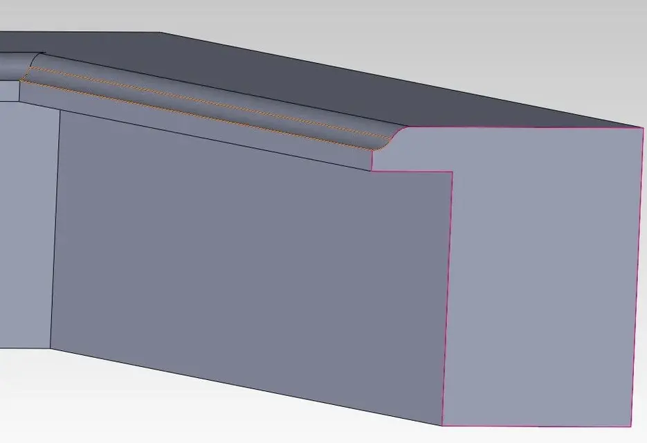
I still face the problem of the incorrect modeling of the faces in a sweep cut that has in this case to follow a 3d sketch. As seen from the attached part file is represented a steady sloped drain channel the first stretch keeps geometric elements like the curvature radius while in the last stretch disappears and becomes a single face...:mad:
 

Attachments

I exempt my argument because..son de coccio.
I still face the problem of the incorrect modeling of the faces in a sweep cut that has in this case to follow a 3d sketch. As seen from the attached part file is represented a steady sloped drain channel the first stretch keeps geometric elements like the curvature radius while in the last stretch disappears and becomes a single face...:mad:
sweeps like lofts are approximate surfaces.
where it manages to keep them analytical, keeps them, where it risks generating 'brutte' surfaces, the approximates.
to have the edges of the rays, maybe you should have used another approach and generate a path without any spline entity.
 
Hi, I downloaded the file and I was doing some evidence but I don't understand why the last cut. I simply modified the 2d sketch of the sweep bringing its height to about 2800....
Moreover, if the last function (extruded cutting) is indispensable, to overcome the problem you tried to add 3d sketches so that you can add additional curves to the sweep function?

I'll pass the modified file. . .
 

Attachments

They asked me to make a rendering of a door... There's no problem I said, two minutes and it's done and I started to create profiles from the frames...drama. the sweep cut I thought was to the ideal function was insufficient. the curved parts in fact are not homogeneous at all and there are discontinuities of surfaces in addition to the fact that if I put on the table something like this does not give a ray of quotation as it turns out to be spline...where wrong?
Bye-bye
I don't know sw but I think it's wrong to approach that some things should be done with surfaces and others with solids

that frame you want to make you must be alive?? I recommend using the surface sweep module and you will see that you can, because with a solid extrusion you will never succeed!!!! unless you reach the edges of the director then you can make a solid sweep otherwise you will always go wrong creating overlaps and cusps

I'll attach your image

sweep green color surfaces

solid grey color extrusion

rest available for clarification

Hi.


Attachments

  • esempio.webp
    esempio.webp
    96.4 KB · Views: 24
I exempt my argument because..son de coccio.
I still face the problem of the incorrect modeling of the faces in a sweep cut that has in this case to follow a 3d sketch. As seen from the attached part file is represented a steady sloped drain channel the first stretch keeps geometric elements like the curvature radius while in the last stretch disappears and becomes a single face...:mad:
in the 'cut-sweep1', remove the flag in the allinea final faces' and the silhouette will be maintained.
To know what that flag needs, I'll send you back to the help.
 
... that then if sketches and paths are done correctly, with the "intermediate passes", the driving curves and axes of half-work when it is the case, the surfaces are perfect; You just have to "check" them somehow.
As soon as I have a moment put that frame that doesn't give problems for resolution... and (for rs4) indifferently with solid or surface (...repeto che catia is another software, suggestions are not stocking :smile:) .

However, as suggested above, that case is best resolved with struttrali members creating a suitable profile. is the fastest method and returns real solids with all differentiated and quotable faces.

greetings
Mar
 
if the profile is of constant section I do not see why it should approximate it. . .
 
in fact it does not approximate... if you put it on the right planes in the right positions and giving it controls for "difficult" direction changes (but this is not the case, that "frame" is quite simple).
placing it on a corner at 90° of the path (out of tangency) can give some resolution problems.

:smile:
 
... that then if sketches and paths are done correctly, with the "intermediate passes", the driving curves and axes of half-work when it is the case, the surfaces are perfect; You just have to "check" them somehow.
As soon as I have a moment put that frame that doesn't give problems for resolution... and (for rs4) indifferently with solid or surface (...repeto che catia is another software, suggestions are not stocking :smile:) .

However, as suggested above, that case is best resolved with struttrali members creating a suitable profile. is the fastest method and returns real solids with all differentiated and quotable faces.

greetings
Mar
I have not intervened as a software but as a type of work saying that any software falls today to do something so elemantere, that is some things must be done with basic surfaces and others with solids because you cannot manage the change of direction in the edges then depends on the section you want to reproduce

greetings

 
I have not intervened as a software but as a type of work saying that any software falls today to do something so elemantere, that is some things must be done with basic surfaces and others with solids because you cannot manage the change of direction in the edges then depends on the section you want to reproduce

greetings

rs4 forgive me but in this case I do not see a difference between doing it solid or surfing.
At least as far as pro/e does not make any difference, if the section in the change of direction does not curl, must behave in both cases equal.
I repeat this on the constant sections:smile:
 
if the profile is of constant section I do not see why it should approximate it. . .
the reason is that the user has activated in the command an option that serves in some cases.
this option makes the section normal to the end face and not normal to the path, in the last stretch.
being the sloped path compared to the final face, this change of inclination in the section creates this shape (the rays on the bottom to understand us).
for those who use parasolid as kernel and if they own this option, they all behave equally.
if instead in this case you turn off this option the result is as in most cad.

As usual, the cad, being a work tool, must be known and in case it was not, these misunderstandings happen between those who use other cad.
 
rs4 forgive me but in this case I do not see a difference between doing it solid or surfing.
At least as far as pro/e does not make any difference, if the section in the change of direction does not curl, must behave in both cases equal.
I repeat this on the constant sections:smile:
it is also regarding catia the surface sweep or solid does the same with different options to set up and does not curl because the control you tell him how to extract the profile vertically then does not create cusps but if not imposed it will go in error, it was only to say paco if it fails with controls in solids or to radiate or to use the classic sweep surfaces that should be more automatic and conson when there are direction changes to 90°

I attach image where does the same thing

grey surface

solid green

greetings


Attachments

  • Sia solido che superficie.webp
    Sia solido che superficie.webp
    93.6 KB · Views: 12
the reason is that the user has activated in the command an option that serves in some cases.
this option makes the section normal to the end face and not normal to the path, in the last stretch.
being the sloped path compared to the final face, this change of inclination in the section creates this shape (the rays on the bottom to understand us).
for those who use parasolid as kernel and if they own this option, they all behave equally.
if instead in this case you turn off this option the result is as in most cad.

As usual, the cad, being a work tool, must be known and in case it was not, these misunderstandings happen between those who use other cad.
Let me say it's misleading.
It is obvious that if I do not draw the normal section to the trajectory it behaves like that.
As far as the cad is a work tool and should be known, I agree, but before that we should also have geometric bases, because otherwise we can never understand why certain behaviors, whether parasolid or granite. . .
 
Let me say it's misleading.
It is obvious that if I do not draw the normal section to the trajectory it behaves like that.
As far as the cad is a work tool and should be known I agree, but before that We should also have geometric bases, because otherwise we can never understand why certain behaviors, whether parasolid or granite. . .
if not it is better to change trade:biggrin: we talk about basic geometry
 
if not it is better to change trade:biggrin: we talk about basic geometry
That's what worries me... .
you are increasingly emphasizing and improving software quality but you are also tremendously lowering the quality of users.
ah how much I miss the old drop-down menus....:biggrin:
 

Forum statistics

Threads
44,997
Messages
339,767
Members
4
Latest member
ibt

Members online

No members online now.
Back
Top