• This forum is the machine-generated translation of www.cad3d.it/forum1 - the Italian design community. Several terms are not translated correctly.

modeling with loft

  • Thread starter Thread starter volaff
  • Start date Start date
Good Saturday to all! !

I tried to make that piece by proving a little the various tips you gave me and that I found really precious! !

I would have one question to ask:
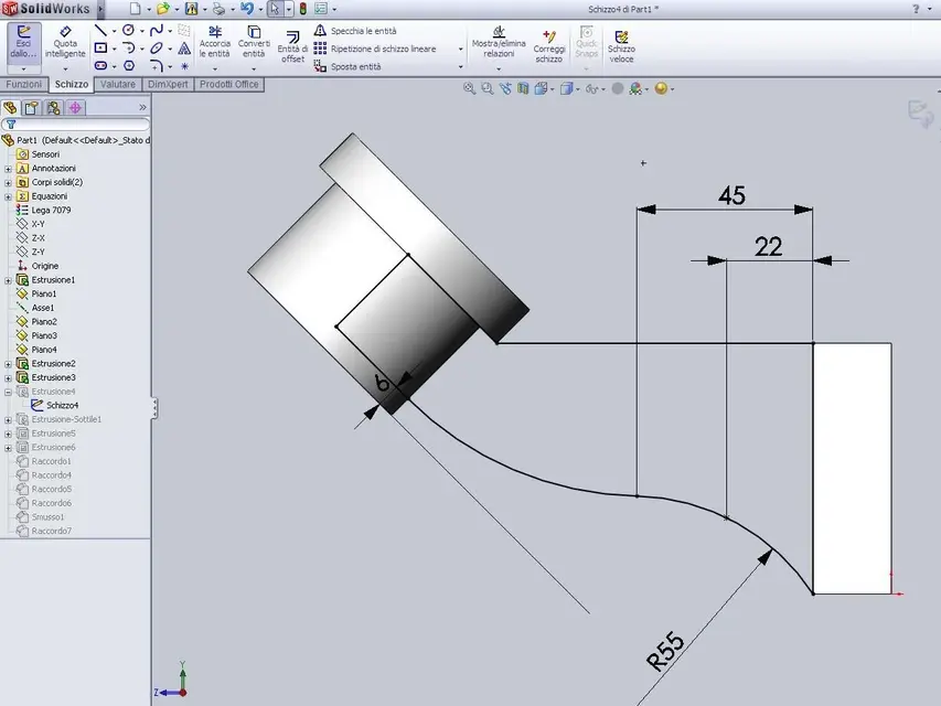
"Where do those odds of 45 and 22 come out necessary to define that profile (which between the later, I think, to realize through the nervation function and see if the thing goes to good end)? "

I can't find her on the drawing!

thanks to all and good day
 

Attachments

  • Immagine.webp
    Immagine.webp
    62.5 KB · Views: 13
"Where do those odds of 45 and 22 come out necessary to define that profile (which between the later, I think, to realize through the nervation function and see if the thing goes to good end)? "

I can't find her on the drawing!
are put to define the sketch completely. There are no drawings.
 
Oh, here you are!

Are you telling me that without such quotas the sketch is not totally defined?

in practice in the drawing there are not all quotas?
 
Oh, here you are!
Are you telling me that without such quotas the sketch is not totally defined?
in swx the sketch is totally defined when it no longer has degrees of freedom, and appears consequently black. you can put the odds even illogically, but sooner or later you get to put the ointment that defines it completely.
in practice in the drawing there are not all quotas?
in your pdf are missing the quotas that accurately define the shape of the rib, so we put it "to feeling".
I add that that representation, horrid, must have made it a strong weirdo... :smile:
 
Big ah! !

Thanks again for the answer.

ps: would you tell me (or send) some drawing to be made with solidworks?

I should prepare for the exam but I did almost all the drawings I had.

Have a good day!
 
of fact glli exercises that I have realized so far are of the type that placed objects in 3d to model with solidworks.

the written test, to what I understand, consists of a piece to be realized but without using axioms.

thank you very much for the interest
 
of fact glli exercises that I have realized so far are of the type that placed objects in 3d to model with solidworks.

the written test, to what I understand, consists of a piece to be realized but without using axioms.
an account is to be able to interpret a table 2d (admitted that they give you that) to pull out the model 3d, another thing is to know how to use the cad to do what you already understood from table 2d.
Let's assume that you know how to interpret table 2d, then you just try to shape anything you see around you because you obviously have to hang yourself with solidworks.

here you would have intriguing examples of mechanical parts, both of fusion and of machining for removal of truciole.http://www.cad3d.it/forum1/showthread.php?t=29105&page=5
 
I forgot. . .
to learn a lot in a very short time about the use of a cad3d based on the history of the model the best way is to "disassemble" a model3d already made, pulling up the insertion bar of the feature manager to understand the succession of features. the same thing is true for sketches, of which you enter for change and understand how they made them.
if you know the basic commands and the working logic of swx (and you are awake) this method for me is worth more than a thousand tutorials

download the most interesting from here:http://www.3dcontentcentral.it/http://grabcad.com/http://www.zxys.com/swparts/http://solidworks.cad.de/library_us.htm
 
Thank you very much. .

ps: I forgot that even the "to pass" the 2d tables would make me comfortable.
the prof sometimes does strange things and would not be the first time it comes with a 2d from which to get the 3d.

Thanks again and apologize for the trouble!

pss: maybe something quoted could help me better!

:-)
 
Here I am. I tried to make that solid through solidworks.

The problem that arises is the following which I attached an image and the model.

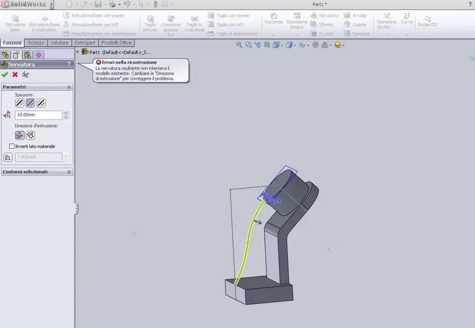
I wanted to make that rib with the same name but the message appears in the attached image.

Usually you have problems of ribbing with cylindrical surfaces but, in that case, the herroe appears that it is not really possible to eradicate ribbing.

In this case it tells me that the ribbing does not intersect the existing model but "eye" does not seem to me.

Am I wrong in anything?
 

Attachments

  • Immagine.webp
    Immagine.webp
    45.1 KB · Views: 12
  • Tavola38.rar
    Tavola38.rar
    67.7 KB · Views: 2
I wanted to make that rib with the same name but the message appears in the attached image.
Usually you have problems of ribbing with cylindrical surfaces but, in that case, the herroe appears that it is not really possible to eradicate ribbing.
In this case it tells me that the ribbing does not intersect the existing model but "eye" does not seem to me.
Am I wrong in anything?
I don't know, in the file I did, with a different procedure, the rib comes even if the profile is on the edge of the cylinder as you did (see image). said this in the design on the pdf that nervation does not come to the face but remains a bit below, if you look well there is the quota at 26 mm, as we did it.
also extrusion4 of your file must be 36 (12+12+12) as in pdf, not 64 as you did. do you see that the shape of the ribbed support is different from that of the design?

already that we are... Why do you draw the base on the front floor? I expect to see what the pdf suggests with the drawing. to orientate in your file there is to freak out :rolleyes:
parts to draw on the right plane, otherwise when you make the table are bitter cabbages.. .
 

Attachments

  • nervatura.webp
    nervatura.webp
    18.9 KB · Views: 6
Am I wrong in anything?
I ran into the file... But you've got the tilted plane handle flying in space, huh? :confused: that plan2 doesn't make any sense, as it doesn't make sense, in this piece, first make the two cylindrical extrusions and then connect them only after the base with the ribbed part.
then: in sketch 4 you made two fittings of radius 15. make the connection of 15 then the other you will have to do 15+12, since it is separated from the first from the thickness of the bracket that is precisely 12 mm.
better yet if you make the exterior concentric to the inner one, so it is tied to the thickness
iho you have to do in this order: base-support tilted-cylindri-nervatura
 
I read all your sympathies and now I'll do everything again.

the ribbing if I put it at quota2 the software realizes it.
I didn't think that if I do the tilted upport then I can easily realize the cylinders.
I understand why extrusion4 must be 6 and not 64.
thank you so much for all your precious seizures!! ! !
 
here... how does it look?


I couldn't make the connection of the ribbing because it always made me mistake.. .
 

Attachments

here... how does it look?

I couldn't make the connection of the ribbing because it always made me mistake.. .
fitting 4 and fitting 5, those of the support, I would do them inside the sketch2, not as fittings but as circle arches tangent and concentric, then quoti the one from 15mm and just. to disegnate strings and consecutive tangent lines exploits the possibility to touch again the summit from which the second line connected that designs, which becomes a tangent arc to the first.
the cut extrusion2 I would eliminate it and change the sketch of the extrusion4 so that instead of being full understand the inner circle that will correspond to the central hole.
if you make a revolution that creates in one blow only all three cylindrical elements (with sketch in the right floor) you can make the complete model using: two extrusions, a revolution, ribbing, three fittings functions and three fittings for cylindrical parts
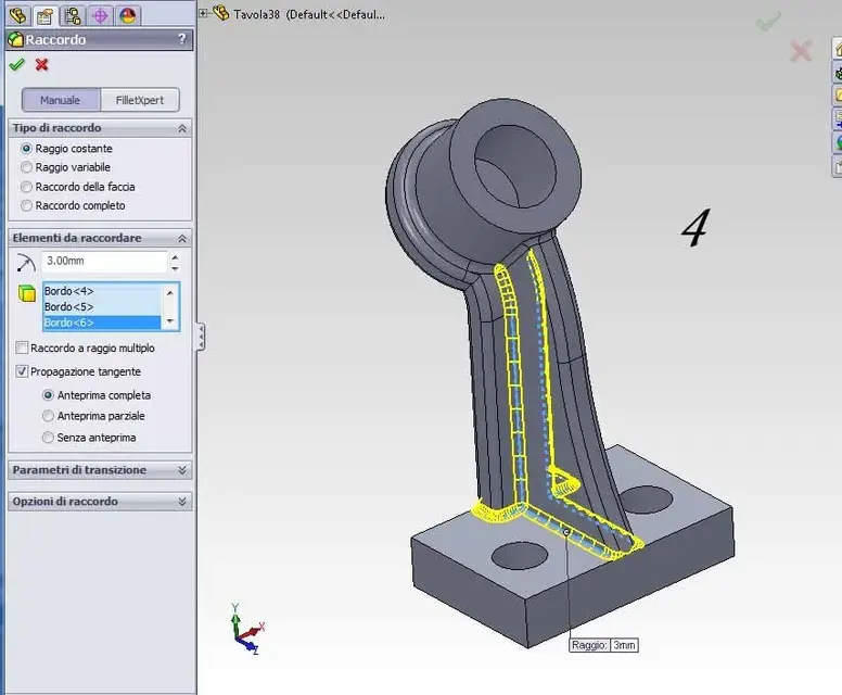
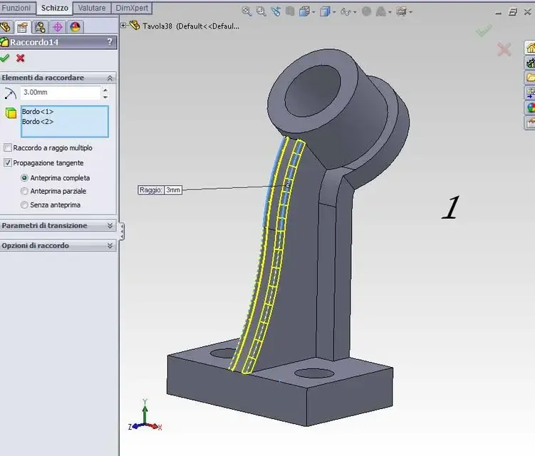
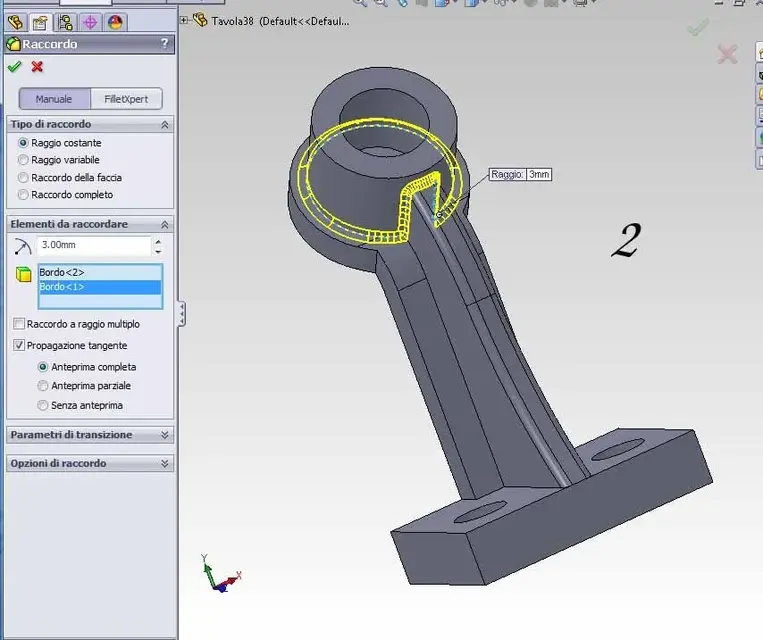
for the fittings, when they fail also depends on the order in which you do them. it takes experience, and those who do for example mergers have so much and perhaps understand to the eye in which order to select vertices or faces to avoid mess. I, who have no experience of fittings but I entrust myself to common sense and ass:smile: I made them in the order you see in the pictures and it works.
 

Attachments

  • 1.webp
    1.webp
    39.7 KB · Views: 9
  • 2 copy.webp
    2 copy.webp
    47.3 KB · Views: 7
  • 3.webp
    3.webp
    48.7 KB · Views: 7
  • 4.webp
    4.webp
    47.1 KB · Views: 8

Forum statistics

Threads
44,997
Messages
339,767
Members
4
Latest member
ibt

Members online

No members online now.
Back
Top