edocad3d
Guest
Hello.
I would point out that this is the first time I write in this forum and I hope that I have observed all the rules in the regulation.
I start by saying that I have searched long and wide on the web the solution to this problem (which is making me nervous a lot these days) but I have not found any solution, I suppose for the particularity of the problem.
the situation is this:
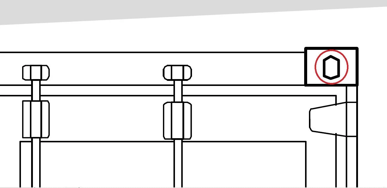
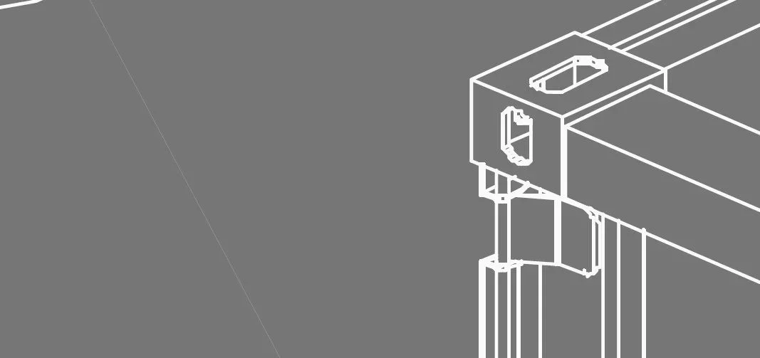
I use autocad 2010 and I am working on a table for the thesis, at the time of printing the table in pdf (as I usually do before sending in print as a plotter so as to check the "real conditions of the work" the lines and the arches present in the drawing (especially those that are part of more complex figures) appear separate between them and moreover some lines come out as if they were a set of broken.
I realize that it is not easy to understand the problem for this I attach an image extracted from the pdf that I have printed with the dwg to pdf tool framed in autocad:
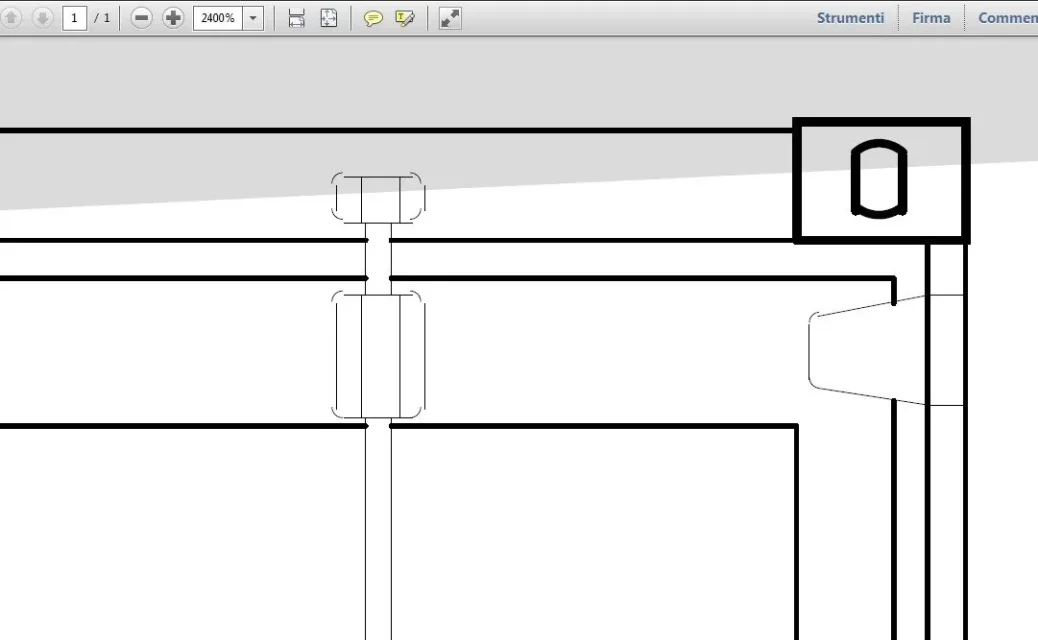

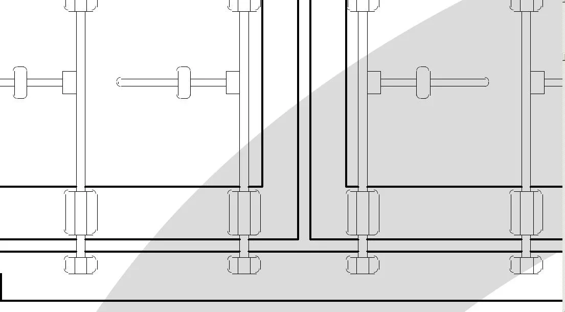 These are screenshots from the pdf file and you notice very well that something does not go in the drawings.
to facilitate the work of those who will be so kind to help me add some necessary clarifications:
- the drawings are all in 2d and I am working on model space and not on layout for the layout
- pdf printing is carried out at 300 dpi and as well as with the dwg to pdf tool has also been made with 2 virtual printers (primopdf and dopdf) and the problem persists.
- clearly in the design of autocad lines and arches appear correctly and not as in the print from pdf
- is not a matter of zeta quota as I have already used autolisp zeta.
- it is not a problem of lines and arches in itself because all the drawings present in the table have been retaken and remade several times to try to solve the problem
I really don't know if this problem is also in print, maybe it's a pdf reader display error (adobe reader) but this seems a very remote possibility. Anyway, it never happened to me and it bothers me a lot.
I hope you can help me. I thank you for your patience and understanding.
Greetings, Edward.
I would point out that this is the first time I write in this forum and I hope that I have observed all the rules in the regulation.
I start by saying that I have searched long and wide on the web the solution to this problem (which is making me nervous a lot these days) but I have not found any solution, I suppose for the particularity of the problem.
the situation is this:
I use autocad 2010 and I am working on a table for the thesis, at the time of printing the table in pdf (as I usually do before sending in print as a plotter so as to check the "real conditions of the work" the lines and the arches present in the drawing (especially those that are part of more complex figures) appear separate between them and moreover some lines come out as if they were a set of broken.
I realize that it is not easy to understand the problem for this I attach an image extracted from the pdf that I have printed with the dwg to pdf tool framed in autocad:
These are screenshots from the pdf file and you notice very well that something does not go in the drawings.to facilitate the work of those who will be so kind to help me add some necessary clarifications:
- the drawings are all in 2d and I am working on model space and not on layout for the layout
- pdf printing is carried out at 300 dpi and as well as with the dwg to pdf tool has also been made with 2 virtual printers (primopdf and dopdf) and the problem persists.
- clearly in the design of autocad lines and arches appear correctly and not as in the print from pdf
- is not a matter of zeta quota as I have already used autolisp zeta.
- it is not a problem of lines and arches in itself because all the drawings present in the table have been retaken and remade several times to try to solve the problem
I really don't know if this problem is also in print, maybe it's a pdf reader display error (adobe reader) but this seems a very remote possibility. Anyway, it never happened to me and it bothers me a lot.
I hope you can help me. I thank you for your patience and understanding.
Greetings, Edward.