vale79
Guest
Good morning to all
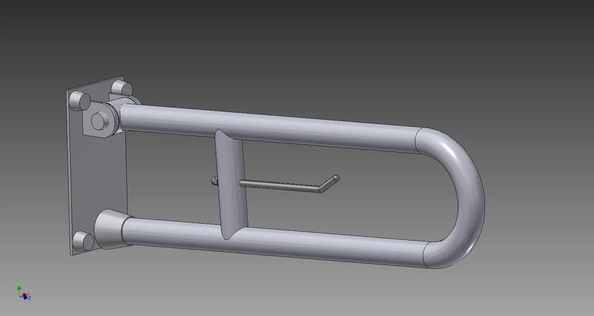
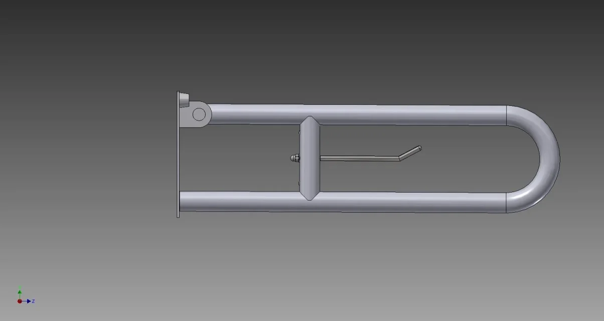
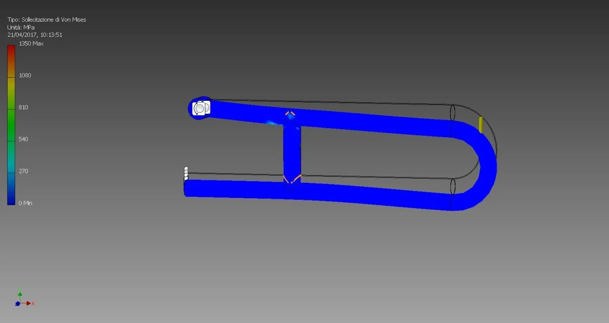
I should do a bearable load analysis from this tipping bar.
I press that a year ago we did 4 hours of course on fem analysis and inventor 2017 (all together), as if we phenomena never saw anything like that then we could be able to do what you do with years and years of experience and studies http://www.cad3d.it/forum1/images/smilies/mad.png so I apologize a priori with whom your work knows how to do it and you do not improvise alllogue from bark like us.
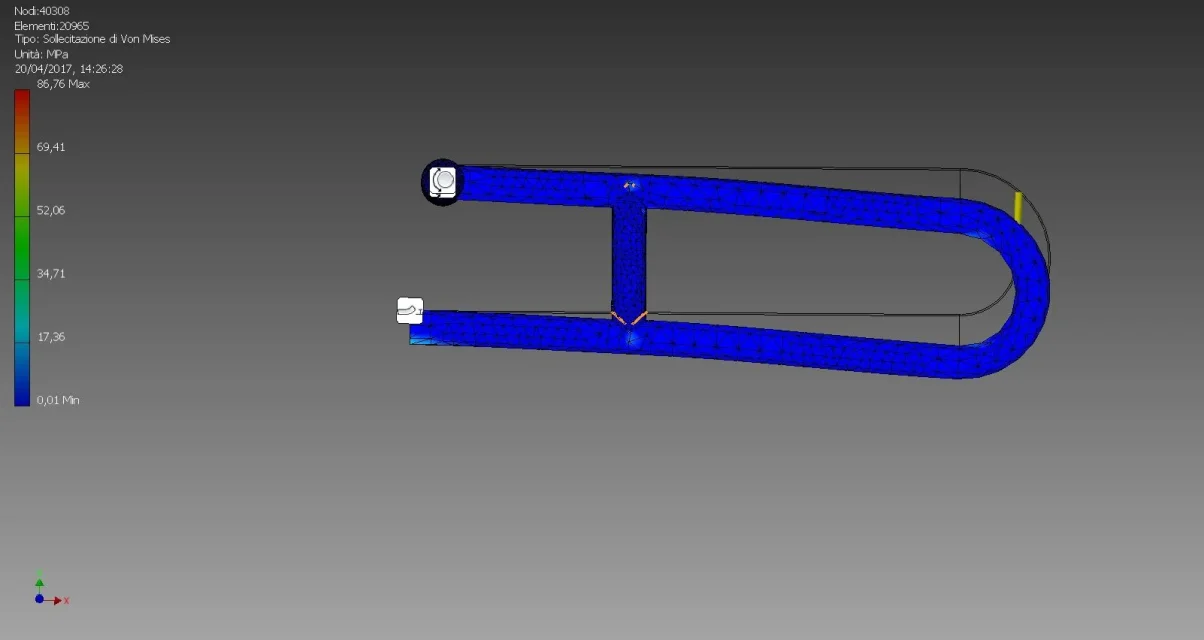
1. I have to realize the welds between vertical traversine and u bar, they will be mig welding with steel intake (all the piece is carbon steel).
I also have to make 4 welding points between the top of the tube and the cylinder in which it is threaded, the one that hides the rotation screw of the bar compared to the plate.
I have no idea how to do (in 4 hours of course we have not seen the welded assemblies)
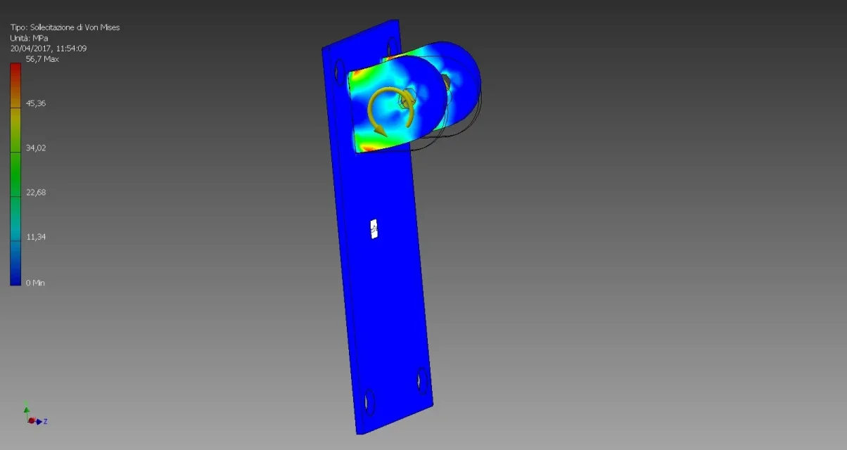
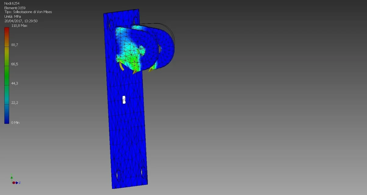
2. I have to do load analysis; here they told me "put a load on the tip of the bar", ok, it is not so much this problem perhaps, but I would like to understand if the result will be a pseudo realistic thing or if it is better to do 2 distinct analysis, one on the plate and one on the bar, etc., I don't think it is useful to blow out a nice colored design of which I don't know nothing only xkè I have to deliver it to someone who knows less than me (the last time I did not even look at a pseudo
I know I should have opened 2 different discussions but I don't know where to start with this, for the moment I preferred to illustrate it in general.
Thank you so much!! !
valet
I should do a bearable load analysis from this tipping bar.
I press that a year ago we did 4 hours of course on fem analysis and inventor 2017 (all together), as if we phenomena never saw anything like that then we could be able to do what you do with years and years of experience and studies http://www.cad3d.it/forum1/images/smilies/mad.png so I apologize a priori with whom your work knows how to do it and you do not improvise alllogue from bark like us.
1. I have to realize the welds between vertical traversine and u bar, they will be mig welding with steel intake (all the piece is carbon steel).
I also have to make 4 welding points between the top of the tube and the cylinder in which it is threaded, the one that hides the rotation screw of the bar compared to the plate.
I have no idea how to do (in 4 hours of course we have not seen the welded assemblies)
2. I have to do load analysis; here they told me "put a load on the tip of the bar", ok, it is not so much this problem perhaps, but I would like to understand if the result will be a pseudo realistic thing or if it is better to do 2 distinct analysis, one on the plate and one on the bar, etc., I don't think it is useful to blow out a nice colored design of which I don't know nothing only xkè I have to deliver it to someone who knows less than me (the last time I did not even look at a pseudo
I know I should have opened 2 different discussions but I don't know where to start with this, for the moment I preferred to illustrate it in general.
Thank you so much!! !
valet