• This forum is the machine-generated translation of www.cad3d.it/forum1 - the Italian design community. Several terms are not translated correctly.

together welded and analysis fem - inventor 2017

  • Thread starter Thread starter vale79
  • Start date Start date

vale79

Guest
Good morning to all
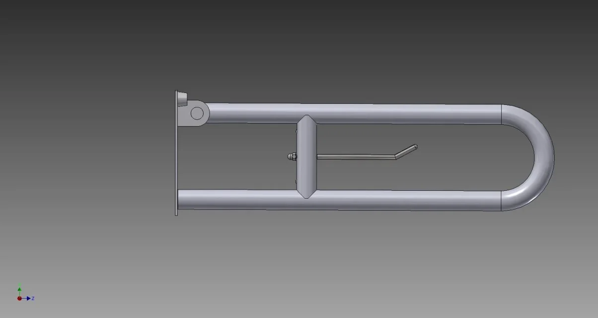
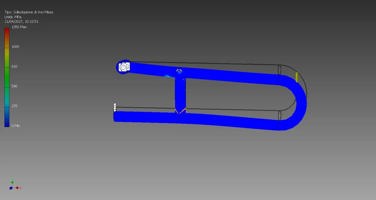
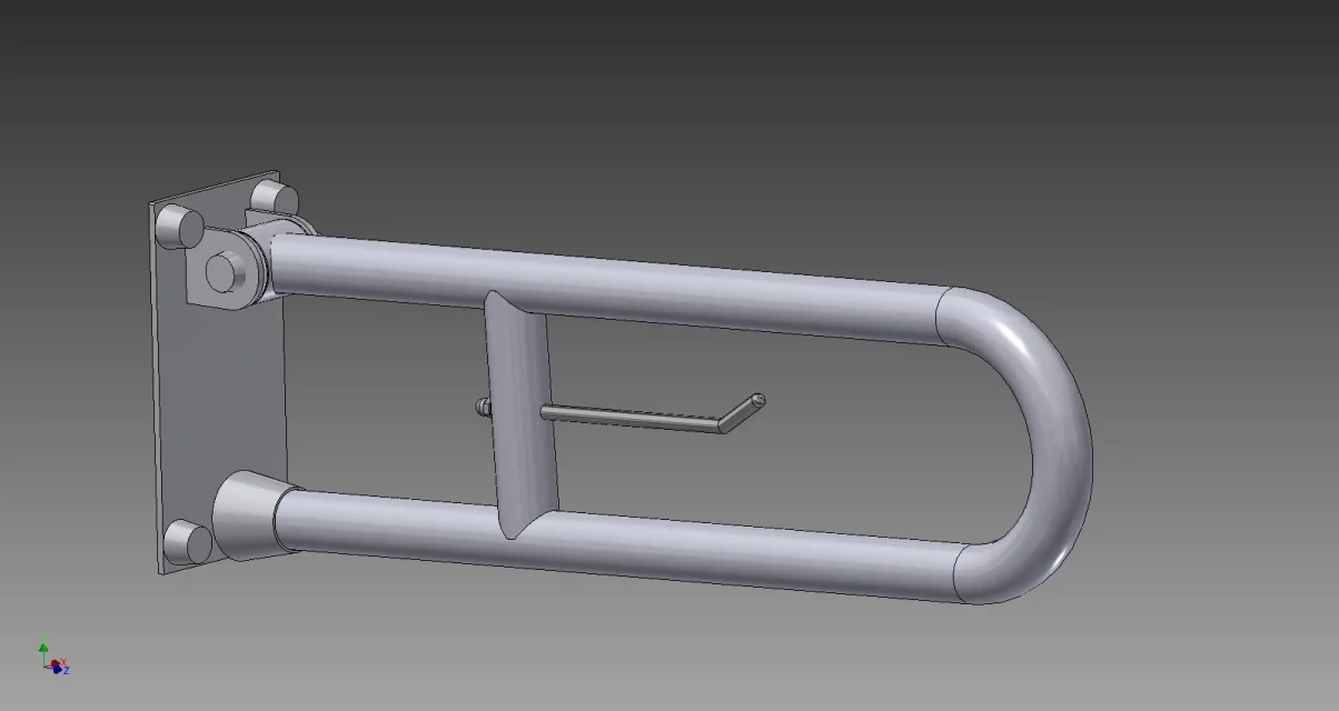
I should do a bearable load analysis from this tipping bar.

I press that a year ago we did 4 hours of course on fem analysis and inventor 2017 (all together), as if we phenomena never saw anything like that then we could be able to do what you do with years and years of experience and studies http://www.cad3d.it/forum1/images/smilies/mad.png so I apologize a priori with whom your work knows how to do it and you do not improvise alllogue from bark like us.

1. I have to realize the welds between vertical traversine and u bar, they will be mig welding with steel intake (all the piece is carbon steel).
I also have to make 4 welding points between the top of the tube and the cylinder in which it is threaded, the one that hides the rotation screw of the bar compared to the plate.
I have no idea how to do (in 4 hours of course we have not seen the welded assemblies)

2. I have to do load analysis; here they told me "put a load on the tip of the bar", ok, it is not so much this problem perhaps, but I would like to understand if the result will be a pseudo realistic thing or if it is better to do 2 distinct analysis, one on the plate and one on the bar, etc., I don't think it is useful to blow out a nice colored design of which I don't know nothing only xkè I have to deliver it to someone who knows less than me (the last time I did not even look at a pseudo

I know I should have opened 2 different discussions but I don't know where to start with this, for the moment I preferred to illustrate it in general.

Thank you so much!! !
valet
 

Attachments

  • 640-I_rest.webp
    640-I_rest.webp
    30.7 KB · Views: 15
I can help you very little.
from what I know you have to turn the axieme, in your case are 2, that of the curved bar and that of the plate, in a welded assembly.
in this go insert the welds with the characteristics you need.

for the fem the result will be realistic if you will set everything correctly.
first of all you need to understand what you want to analyze, define constraints, loads, materials, etc. and then you will have a reliable result.

What do you need to check? the strength of the welded plate? the curved bar?
what are the loads to which it is subject? and the constraints?

more info put more precise will be the answers.
 
Thank you.

Now I'm trying to put welds on the plate which is the easiest part. in this case welds should not be made at corner on the sides of the fins, but the plate has 2 grooves in which the fins are inserted and then from behind will be welded to mig and shaped wheels.
I tried to make a bevel as part preparation but does not take welds, I certainly gave him wrong inputs. takes the simulated welding, can it be okay? What changes between the simulated one and the others?

for the fem:
wall- bound plate through the 4 holes, we can consider it fixed completely as to me affect the resistance of the plate and that of the bar, not the resistance of the wall fixings.
then the legislation says to apply a load of 225 kg (in our case) to the most unfavorable point, then the curve end of the bar. Whereas it is used by people I think it is not necessary to put the load on the curve, possibly even at the end of the straight part before the beginning of the curve is fine.
 
rectifying, welds on the bar (between the traversine and the pipe to u and between the pipe to u and the cylinder that hides the rotation screw) are a mig with steel intake, the welds behind the fins of the plate are tig
 
you could fix the plate with a fastener on the back wall and apply the load on the bar.
Of course, focus on materials, then you will check the tensions that are created in critical points.
so to the eye I would say on the solicited cutting pin and on the welds.

I would also do an analysis on the only bar by binding the pin, bottom support and applying the load.
just to verify the resistance of the bar.
 
so it's a ca...a?
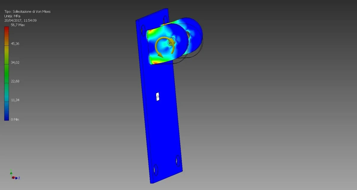
I put a moment of 225 kg * 600 mm (bar length) applied on the sides of the fins.. .
of these bars I have tried many in fact under the press and I have seen that the more it tends to deform is the fins that close towards themselves, for this I have applied the moment to the faces.. .
carbon steel breaking load is about 360 n/mm[SUP]2[/SUP] So the result would look good...
as a simulated welding surface I made 4 0.2 m^2 cords that seems to me an exaggeration, but I have no idea how it will actually be
 

Attachments

  • SFT-REST_saldata_momento su piastra.webp
    SFT-REST_saldata_momento su piastra.webp
    27.2 KB · Views: 18
I think I'm moving.
Where did you apply it?

I would argue differently, you have the force applied at the end of the bar and the same which is leaning on the plate.
the center of the moment is not the pin, if not mistaken.
 
now I have brought the value of the cords to 0,00007 m[SUP]2[/SUP] that is a much more realistic value I believe and I applied the moment in the lower part of the fins. Maybe it was applied in the top but I don't think the result changes much.
 

Attachments

  • SFT-REST_saldata_momento su piastra_3.webp
    SFT-REST_saldata_momento su piastra_3.webp
    46.2 KB · Views: 12
Yes indeed, I did not want to apply the moment on the pin but on the fins... I don't know exactly where...
In practice I believe that the effort is distributed in part on the bottom terminal of the bar, that with the rubber tip (which serves to maintain the bar in horizontal position but under load you cut), and in part on the upper part of the fins, as if you want to tear pull down, and then in part also on the welds that hold them attached.
but it is possible to apply a force in the real point of application, then distant from the plate? How do you know where the reagent force will be?

that is, we put that my real force is only vertical, 600 mm distant from the plate.
to simulate it I should apply a force up to the base of the wings, right?
but this is not the real situation because the hole moved compared to the base of the wings creates cmq a moment that tends to tear them, and I apply only a vertical force I lose this component.
 
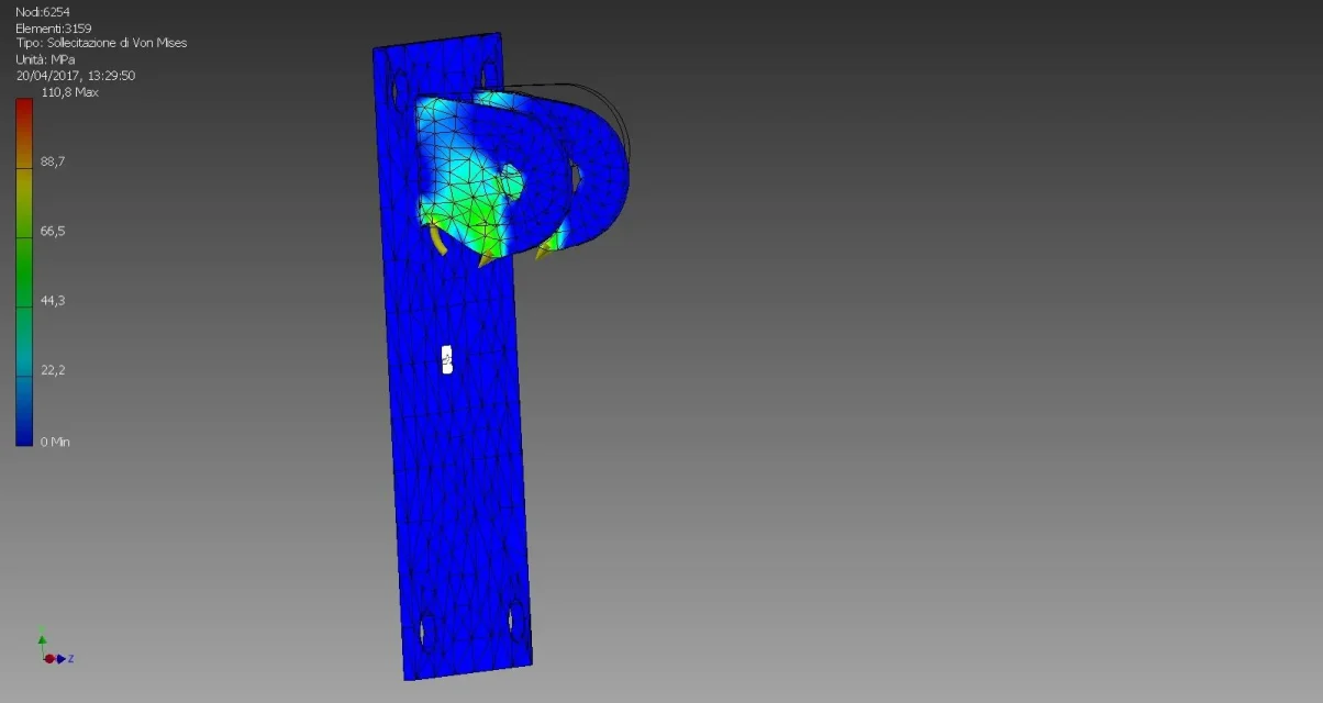
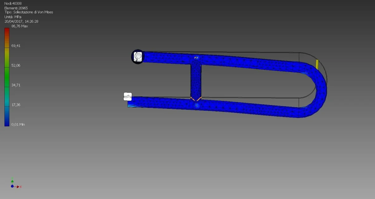
done. . .
I feel like something's wrong. in reality the shift of the final part I think is much more so.
 

Attachments

  • Barra 600_rest_saldata_1.webp
    Barra 600_rest_saldata_1.webp
    38.1 KB · Views: 12
  • Barra 600_rest_saldata_2.webp
    Barra 600_rest_saldata_2.webp
    57 KB · Views: 14
Yes, a little more. half a millimeter is very little, it would be exceptional.

what I have seen in reality though is that it is enough to get wrong little and the bars are piled up like paper.

In reality we try them complete, including the rubber tip at the standpoint.
at the beginning of the test they have a good armor (particularly given by the tip) and at the end they turn out about horizontal because the tip is cut. but the armor is very important because without that the load endured becomes lower, of much, this because if the final part of the tube (that in the tip) instead of leaning horizontally leaned only on part of the face of the tube (because for example the bar is inclined with a angle less than 0 than the horizontal) the tube crushes just like the inner roll of the toilet paper and the bar falls.

cmq if you tell me that more or less could be better.

the supplier who built the bar said that he tested it under a very high load and did not bend (in the side direction;-) ), and is a super technologically advanced and doing things very well, I do not know if he did also simulations to the pc but of his test under load I trust 100%. We tried it here, too. She did well. I just seemed very small as a deformation value but at this point it must be my wrong impression.

Thank you so much!!! ! ! ! ! ! ! ! ! ! ! ! ! ! ! !
I would never have done it without your advice.
 
eye, my thoughts are made without knowing the problem well.
Since you have other similar details that you have empirically tested try to apply the analysis to those too.
If the same values return, about, that you have found on the evidence, then you can trust the analysis.
if the values are very different you will have to review the setting completely.

I have not understood the speech of the armor, moreover in your analysis the rubber tip is not considered.
the deformation is all of the tubular and all in the stretch after the vertical reinforcement.
I do not know diameter and thickness of the tube, but the deformation does not seem particularly high for that applied load.
 
the safety factor depends a lot on the type of product you go to realize.
in aerospace, for example, if they are not mistaken they are obliged to hold a security value 12.
if the breakup of the component can cause damage to people or, worse, death should be kept on those values.
some fields are regulated in that sense, others are left at the discretion of the designer/business.
 
we use the standard on products for disabled requiring a test load 1.5 times higher than the declared load, so we declare a bearable load of 150 kg and test the bar to 225 kg (for 1 minute). We do not use other safety coefficients for individual parts.

As for the armor, we try the product with the rubber tip (which serves to protect from crushing the fingers for children and disabled) and keeps the bar tilted upwards compared to the horizontal.
if we remove the tip the angle would be less than 0 and the terminal part of the tube would be as in the second photo, practically only with a circular sector instead of with all the base surface. the tube is a 32x1.5 and if it only supports with a sector it crushes like butter collapsing on itself even with very low loads.
what I wanted to say before is that by looking at the real evidence under the press all the corner occupied by the rubber pointer shows a remarkable movement of the bar, so it seemed to me that 0.5 mm were few, but it is absolutely personal and without real foundations that can make me doubt the result obtained.

what came to my mind as a huge doubt is.... as a load I put 225 thinking about the 225 kg of the real test, I should have put 2250 n. ? ?http://www.cad3d.it/forum1/images/s.../www.cad3d.it/forum1/images/smilies/frown.pngThank you very much
 

Attachments

  • 640-I_rest_arm.webp
    640-I_rest_arm.webp
    20.3 KB · Views: 5
  • 640-I_rest_no arm.webp
    640-I_rest_no arm.webp
    13.6 KB · Views: 3
  • 640-I_rest_zoom.webp
    640-I_rest_zoom.webp
    7.2 KB · Views: 3
the rubber tip will deform a lot with that load and that lever.
the analysis you did not take into account the tip but consider the tube bound, the deformation you see is all of your welded structure.
if you have the available press make a test without a pointer by inserting a thickness under the tube so that the angle is 0 and the support is on the whole top of the tube. then check if the deformation returns. in this way you can validate the analysis and repeat it in the future.

the load is expressed in n, you have to make the transformation.

One thing that seems strange to me is the crushing of the tube you say occurs when applying the load.
Do you have any image of a case? just for curiosity, to give me a more precise idea.
 
unfortunately I can't find the original photos anymore, I try to allegar you this: the part that I highlighted in yellow folds towards the inside, just as if the pipe fell on the floor beating with a angle different from 0 or 90° (and of course from an adequate height to deform it).

cmq I would say that the first thing to do is remake the analysis with the right load in newton http://www.cad3d.it/forum1/images/smilies/frown.pngI can do it. tests have already been made with the tip and the product is ok, but we just miss the passage to validate the analysis with inventor regarding the actual tests.
For example, the fact that the tube is not bound down while I have given it a rigid bond is not realistic. would be better a vertical scrolling bond? or simulation on the complete piece, i.e. plate and bar connected with the rotation screw? in this case I have to check the "Relevance and Deletes Hard Body Mode" box?
 

Attachments

  • 1.webp
    1.webp
    255.3 KB · Views: 3
Okay, now I have a clearer idea.
as a constraint I would use the "private of friction".
in that way consider the piece as leaned but free to slide on the plane, as it is actually your particular.
if doing the analysis on the single piece or the axieme depends on what you want to go to analyze.
if you want to see the resistance of the bar analyzes only that, they are easier analysis to do.
One thing you could do is analyze the bar just as it is in reality if you don't put the rubber toe.
you could make a small face with the tilt that has the bar when it is leaning without a pointer, then bind that.
so by concentrating the reaction to the load right at that point, you should see very high tensions in the collapse zone.
I don't know if I explained.
 
Yeah, got it. In fact I would like to see if I can reconstruct this thing of the tube that collapses, after I try; you can do (extremizing) also shortening of 1 cm the final part of the tube, the one that supports and that it will collapse. a few years ago a supplier made us miss a lot like this and that disaster, we had to dispose of hundreds of pieces.
I tried to change the load in 2250 newton and obviously the result is not good even if I did not change the :frown scale:, so there must be something wrong in the rest of the analysis.
Now I try to do it on the whole bar also because in reality the load is endured by the assemblies, not by the individual components, right?
 

Attachments

  • Barra 600_rest_saldata_3.webp
    Barra 600_rest_saldata_3.webp
    24 KB · Views: 4
  • SFT-REST_saldata_momento su piastra_4.webp
    SFT-REST_saldata_momento su piastra_4.webp
    48.2 KB · Views: 7

Forum statistics

Threads
44,997
Messages
339,767
Members
4
Latest member
ibt

Members online

No members online now.
Back
Top