gianni55
Guest
Hello reader,
I also sought a more neutral export. . .
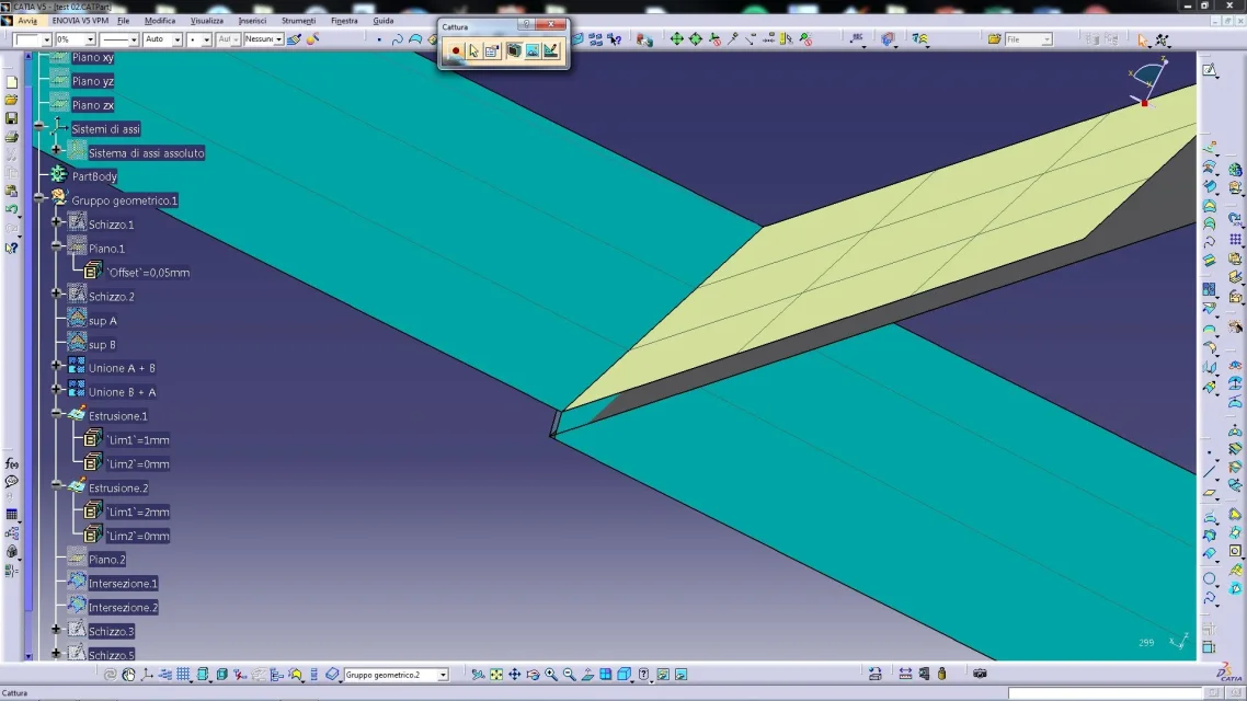
the join and optimization of the surfaces are possible only in the import (and I did not even use them when I reimported the file)
in the export iges I used:
save only displayed entities: Yes.
type of curve and surface: standard
mode of representation: surface area
in export step I used:
Protocol: 214 iso
import iges I used:
no optimization
representation of the edges and faces: preserves file preferences and I also tried strength 3d representation (equal result)
import step I used:
no optimization
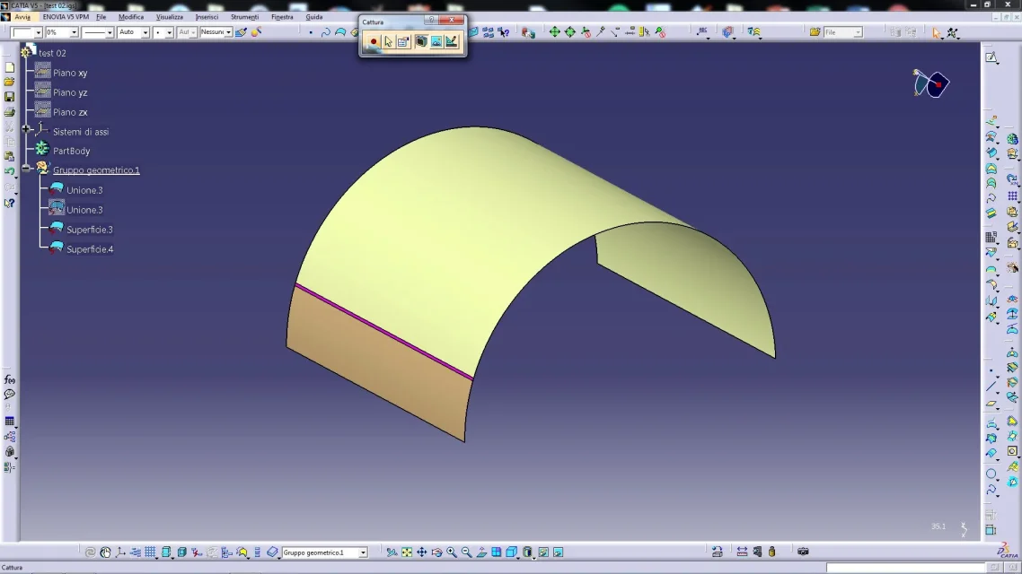
the step loads a solid surface, and if the disassembly echoes 2 surfaces that reflect the deformation
a colleague loaded iges and step with nx with similar results
I also sought a more neutral export. . .
the join and optimization of the surfaces are possible only in the import (and I did not even use them when I reimported the file)
in the export iges I used:
save only displayed entities: Yes.
type of curve and surface: standard
mode of representation: surface area
in export step I used:
Protocol: 214 iso
import iges I used:
no optimization
representation of the edges and faces: preserves file preferences and I also tried strength 3d representation (equal result)
import step I used:
no optimization
the step loads a solid surface, and if the disassembly echoes 2 surfaces that reflect the deformation
a colleague loaded iges and step with nx with similar results


")