• This forum is the machine-generated translation of www.cad3d.it/forum1 - the Italian design community. Several terms are not translated correctly.

parallel axle speed reducer

  • Thread starter Thread starter Kekko999
  • Start date Start date
As for the maximum inflexions of the trees, are there limit values to be respected? by kisssoft I have the results and I wanted to compare them if they were reasonable or not...
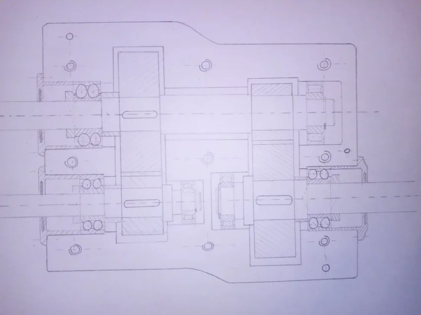
kisssoft computed flessions are evaluated taking into account the variation of ingracing, so it really tells you whether it is excessive or not.
in mechanics, very general concept, it is considered a mechanical component (non carpentry) rigid if the arrow is less than l/4000 where l is the tree light between the bearings. definitely for medium/good precision gears it is necessary to reduce even a little bit maybe l/6000.
the question of the arrow is very complex for the gears.
 
Good morning, everyone. I spoke to my prof. and advised me to change the assembly of roller bearings: inner ring fixed with shouldering on tree and seeger, free outer ring (without ring for holes and spacer). @meccanicamg What do you think?
 
Good evening, on shape I shaped the tooth profile of the pinion and joining the sweep with the circular matrix gives me this mistake I didn't have on the wheel, you know how I can solve it?
 

Attachments

  • problema sweep.webp
    problema sweep.webp
    88.8 KB · Views: 37
Good morning, everyone. I spoke to my prof. and advised me to change the assembly of roller bearings: inner ring fixed with shouldering on tree and seeger, free outer ring (without ring for holes and spacer). @meccanicamg What do you think?
Surely the outer ring cannot be thrown into the hole without the limits given by jokes and spacers.
However try to make a drawing draft and we comment.
 
Good evening, on shape I shaped the tooth profile of the pinion and joining the sweep with the circular matrix gives me this mistake I didn't have on the wheel, you know how I can solve it?
where does the profile come from? There might be some zero thickness error...
 
I tried to search on mebac but there are files only for straight teeth wheels
Surely you need the profile in 2d and then build the propeller by sweeping on arc or propeller industry.
if the goods you want the 3d model simply putting the main data I recommend freecad with the fcgear module so download the 3d in step format.
 
Surely you need the profile in 2d and then build the propeller by sweeping on arc or propeller industry.
if the goods you want the 3d model simply putting the main data I recommend freecad with the fcgear module so download the 3d in step format.
I made the model with freecad, but how to download it to make it compatible with catia?(if you can))
 
Surely the outer ring cannot be thrown into the hole without the limits given by jokes and spacers.
However try to make a drawing draft and we comment.
side zipper a radial double spheres locked inside (shoulder and wrench) and external (shouldering on carter and cover), side cart a cylindrical roller locked inside (shoulder and seeger) and external free. is it correct?
 

Attachments

  • IMG_20201108_185021.webp
    IMG_20201108_185021.webp
    53 KB · Views: 30
the roller bearing you chose has the outer ring coming out of the bearing. Look at your lips.Screenshot_20201108_202710.jpgas I told you in previous posts....for the bearings that you mounted (nu) you have to put the jokes with the spacers on the outer rings because the slide takes place relative inside the bearing.
The nj series is monodirectional while on the other side it stands....while nup is the bearing that you have to mount because so you do not put the spacers but you do not lose the rings axially.
look at the image above well. Put a finger on the inner ring and push... .

otherwise you have to put the spacers.... but then you should send me notice the seeger on the outer rings.d005cc55-249f-42de-bfc6-8dafb231a95f.png
 
Last edited:
the roller bearing you chose has the outer ring coming out of the bearing. Look at your lips.View attachment 59870as I told you in previous posts....for the bearings that you mounted (nu) you have to put the jokes with the spacers on the outer rings because the slide takes place relative inside the bearing.
The nj series is monodirectional while on the other side it stands....while nup is the bearing that you have to mount because so you do not put the spacers but you do not lose the rings axially.
look at the image above well. Put a finger on the inner ring and push... .

otherwise you have to put the spacers.... but then you should send me notice the seeger on the outer rings.
[/QUOTA]seeing the solution with the prof advised me to lock the inner ring with seeger and remove the two rings (distantial and for holes) on the outside... So with nups are right? without binding the outer ring
 
regarding elements such as rings, spacers, rosettes, screws etc. is there a bookcase directly on the caty or the sites where you can download cad?
 
sites from which you can download standard mechanical components in neutral formats: https://www.mcmaster.com/ (American)
bearings, needles etc directly from skf.com
 
regarding elements such as rings, spacers, rosettes, screws etc. is there a bookcase directly on the caty or the sites where you can download cad?
traceparts has all commercial elements, as standard and all kinds.
Spacers don't exist from business but you make them drawing.
screws, rosettes, wreaths, seeger etc. find them because as a rule.
 
Keep in mind that the nup bearing becomes axially rigid so you will have to allow the scoring for expansions leaving the outer ring free.
the nu bearing need two shavings of locking outer ring,
as it was said, obtained directly in the case without space, if you opt for the case divided in two half. In this case the nu bearings work better because the inner ring is free to flow without loading the flat face of the rollers against the reservoirs, as happens in the nups, which push the outer rings because of the expansions. It is intuitable that in this case there is a friction for crawling between flat surfaces, and therefore at this point it would be necessary to use ball bearings or barrel rollers that explicate the thrusts for volve friction.
therefore also consider the calculation of the bearing to make subsequent choices.
 

Forum statistics

Threads
44,997
Messages
339,767
Members
4
Latest member
ibt

Members online

No members online now.
ciao
Back
Top