Kekko999
Guest
Good evening to all,
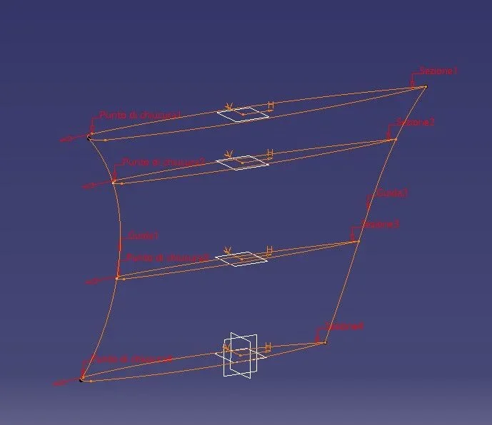
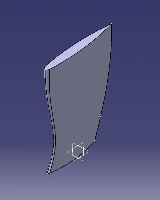
I am working with catiav5r20 for the realization of the vertical rudder of the boats of the next america's cup 2021 and I have a problem to ask: I brought with excel the coordinates of the profile, an eppler 520 and I have to join the two profiles at the ends following a certain design; I would need to model the profile along the opening without connecting the two profiles from a straight and use the solid multi-section command. practically it is as if the rudder had a variable rope when the "wing" opening increased from the root to the end (we imagine that the rudder is a wing). place two photos showing my model without change in opening and then a photo of the royal rudder that highlights the variation of rope on described.
the question is: is there a default command or should I use special procedures? Thank you in advance. (you will not see in my cad the horizontal part of the rudder that I will go after to assemble).


")
