Shotfree
Guest
good morning to all of you, I should make a folded pipe with a cut that allows, for the precisely bending (a little like a sheet), I thought of the svergola and the deformation according to trajectory, but I can not find the square, someone has right about it?
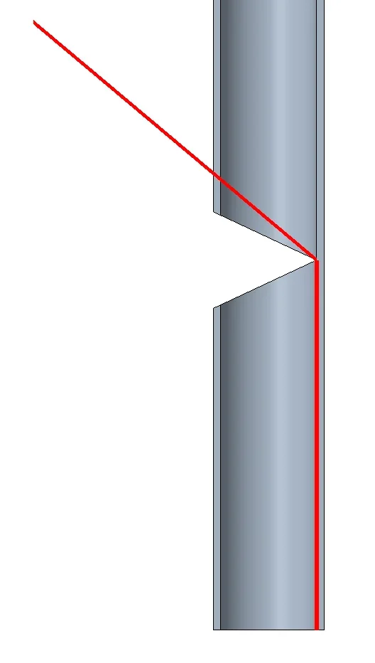
to understand us as from image (in red the final result I would like to get).
 Thank you for your help!
to understand us as from image (in red the final result I would like to get).
Thank you for your help!") )
)

 :coffeee::coffeee: