• This forum is the machine-generated translation of www.cad3d.it/forum1 - the Italian design community. Several terms are not translated correctly.

3d axle alignment

  • Thread starter Thread starter mauror
  • Start date Start date

mauror

Guest
Good morning to all
I'm struggling with a problem I can't handle.
I can also find it difficult to explain so I attach an image.

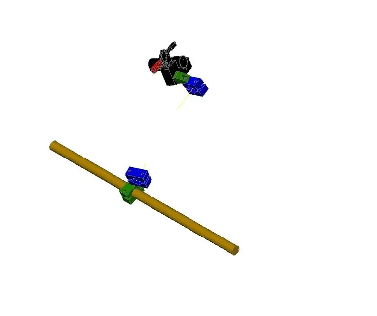
the amber color tondino as well as the support with clamp are fixed (the support with clamp varies the position according to the piece to work). on the amber tondino is mounted a band (green) that can slide and rotate on the tondino. another face (blue) is mounted on the green one on the passing hole of the screw and has a rotation movement.
On the other hand, on the support with clamp there is a green trangolar that has a rotation movement. to this is mounted a band that also has a rotation movement.

I have to align the axes of the two blue faces so that we can pass a round. I also attach the dwg for those who want to see it better.

If you can give me a tip I thank you infinitely.
 

Attachments

  • ex1.zip
    ex1.zip
    112 bytes · Views: 6
  • ex1h.webp
    ex1h.webp
    12 KB · Views: 14
Last edited by a moderator:
you have to create 2 additional ucs, saving them with names (I used v1 and v2 but are arbitrary)
the one in the plant already you have it (the world)

move the second clamp on the first, (I noticed that you already have the yellow axis) then move you on each ucs and rotate until the axis does not coincide (ruote reference is the fastest command)

The rotation is to be done for each bird.
once aligned, command ucs object and select the axis. save it and then move the piece with the garden where you want
 

Attachments

  • ucs.webp
    ucs.webp
    6.1 KB · Views: 5
arranged with the operations mentioned above.

There are also 2 ucs (piece axis and perp piece), so that it can still rotate

Bye.
 

Attachments

thanks for the answer, I noticed that so the lower face of the green triangular solid (the one connected to the support with clamp) and its clamp do not have the same axis (the axis that crosses both).
 
Mauro, I didn't move any of the pieces from their original assemblies.
I have only aligned the two yellow axes, and then moved and rotated a set (steel+draw) compared to the other (face+morse).

all cases, to obtain a 3d rotation in autocad, the most intuitive method is to create a ucs that has the x and y axes lying on the plane in which the rotation is carried out, so as to have the z axis that acts as a "spillo" of a compact imaginary.

Try to make you a ucs that has as z the magenta axis of the clamp hole and then rotate the items you want.
 
I'm wasting a lot of time with this thing, I'm sure I'm not clear about the use of the ucs, it's because I'm not running it.
 
test with line.

p.s. I moved slightly one of the two groups from the initial position, so as to make the procedure more evident.
 

Attachments

thanks gp of the contribution but it is not exactly what I meant, with your solution you moved the support (the black one) while it has to stay fixed.
I'm trying to get back.
the black support must remain in that position, you can not move, as well as the amber color cylinder.
to the black support is connected a bracket (green). this bracket can rotate on black support according to the shared axis between the two elements.
the bracket is connected a blue clamp, also this can rotate on the axis in common with the bracket.

on the other side: the amber cylinder of diameter 40 is fixed. on this can scroll and rotate a clamp (green), to this green clamp is connected another clamp (blue), this can rotate on the axis in common with the green clamp.

both blue clamps have a yellow axis, according to the movements that can perform the elements I must make the two yellow axes coincide.
Thank you.
 

Forum statistics

Threads
44,997
Messages
339,767
Members
4
Latest member
ibt

Members online

No members online now.
ciao
Back
Top