• This forum is the machine-generated translation of www.cad3d.it/forum1 - the Italian design community. Several terms are not translated correctly.

aircraft panel: problem and advice

  • Thread starter Thread starter volaff
  • Start date Start date
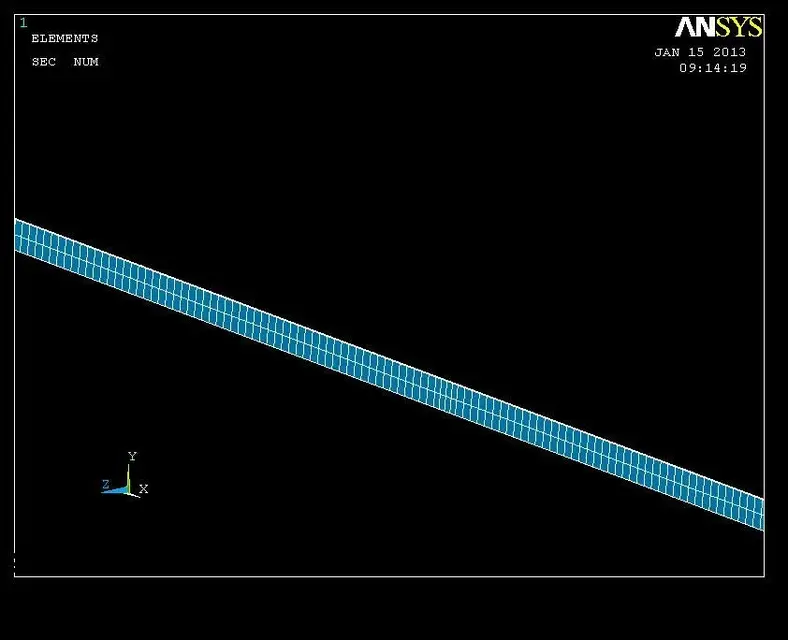
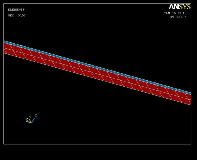
the distance between the stringer and the red panel is 1.4 mm, I don't think that's the problem. .


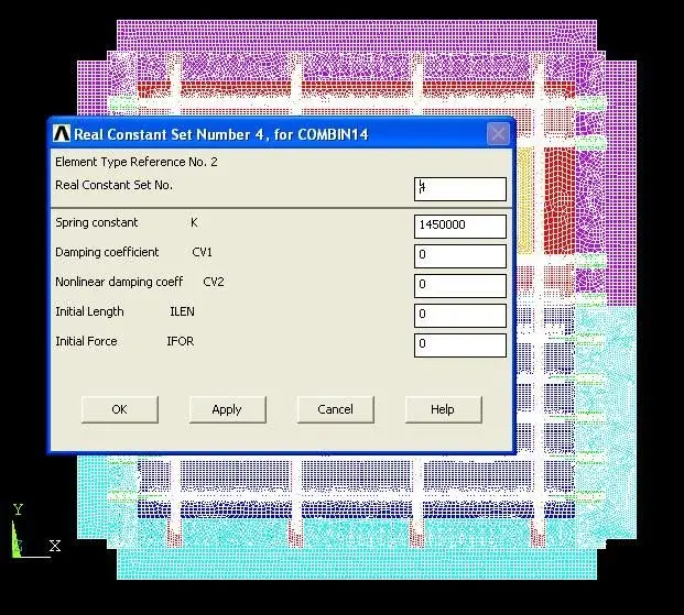
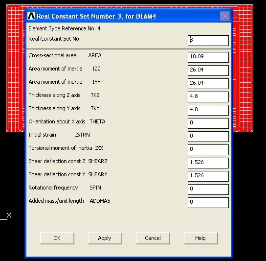
I had thought of putting for the overlap zone of the panels, infinitely rigid rivets but on the following screen:

stiffness.png


multiply, for example, all values per 1000 could be an idea???? ? ? ? ? ? ?

Thank you so much again.... heart!
 

Attachments

  • stiffness.webp
    stiffness.webp
    27.6 KB · Views: 10
Last edited by a moderator:
If I understood correctly, you shaped the rivets with beam elements4, giving the properties of the rivet section. 4.8mm diameter, inertia of a 4.8mm full bar.
Now, the main difference that I see is due to the fact that rivets only work by cutting, as the plates are joined together.
the elements that you shaped flettono as they have a finite length.
I think you should increase the flexional stiffness, leaving the cut unaltered.
to verify the theory tries to evaluate the flexional stress in the beam 4 element.
if stress is high it means that the element has a remarkable flexional load and therefore also a deformation. in which case I would increase the iyy and izz leaving the area unchanged and therefore the cut stiffness.
another thing missing in your model is the contact between the sheets. the rotation of the rivet is not allowed by the fact that the sheets are in contact, modeling only the rivet and not the contact the sheets are free to move as they want and then to flex the rivet.
increasing the flexional stiffness of your rivet compensates for the lack of contact (I imagine that you do not want to do an analysis with contacts) and simultaneous the fact that the rivet stuck between the two plates can only work to cut.
 
I don't know, in my opinion, the problem depends more than anything else on the fact that the blue and rock panel is not fully bound by simulating the bonding across the entire overlapping surface.
 
thanks wave for the answer and thanks also to matteo, as always!

here are the images of the bending (moments) to the heads of the rivets (node i and nodo j) for my and mz.

increase izz and iyy yes, but how much?! multiply by a factor thousand!?

cmq we decided to avoid contacts (even if they solve several headaches apparently).

thank you so much to both for the disponibility! ! ! !
 

Attachments

  • 1.webp
    1.webp
    19.2 KB · Views: 6
  • 2.webp
    2.webp
    19.2 KB · Views: 4
  • 3.webp
    3.webp
    19.2 KB · Views: 4
  • 4.webp
    4.webp
    17.1 KB · Views: 3
error or ansys smn and smx are minimal and maximum stress and are not moments as you wrote. I don't know. I haven't used ansys for so long, but that sounds like it.
If so you would have a maximum stress of -5800mpa (uses mm and n?) that seems to me excessive and indicates that your rivet works as it should not.
Unfortunately, as Matteo rightly says, if the glue is present and is not simulated, it is very likely that the result differs from reality.
in your situation, you have two plates with an offset between them, which exchange a traction/compression force, which due to the offset becomes bending in the rivet.
as I told you before, increasing the flexional stiffness improves the model, although I have the doubt that it is only a palliative. You seem to me that you have only one row of rivets, which behaves like a hinge. completely neglecting the fact that the parts are glued.
If you do not want to use contacts to simulate glue, you should, in my opinion, meshare parts to coin knots on the common surface, turning the shell offset to the correct side, to maintain the real offset of the plates.
insert between the matching knots of the spring elements referred to by the correct cutting stiffness of the considered adhesive.
These elements are adimensional and have as input only of stiffness, in nastran they are called cbush, I imagine they have also correspondents in ansys.
small detail, as for each knot you have to insert the stiffness of the glue area surrounding the knot, the mesh should be as far as possible made with elements of the same size. :mad:

If you want to do a test with your current model, it also increases the flexional stiffness of a factor 1000 and see what happens, the basic pattern is missing of the glue, so it is not correct, also concentric the transmission of the bending moment in a few points (the rivets) instead of glue. It doesn't cost anything, but it gives you an idea if the road is correct.
 
here you find a treatment of how to treat stickers (nastran)http://femci.gsfc.nasa.gov/adhesive/index.htmlthe elements to which it refers are the old celas that set a stiffness for each direction (three elements for each node) now you can use the cbush elements.
I think you can do a similar treatment even in ansys, as long as you can make mesh to similar area elements.
unless you write a routine that reads all the elements attached to a knot, calculates the area and creates the elastic constant depending on the area..... .
 
Dear wave thank you for your answer.

the hypothesis, or rather the modeling specification, concerning the glue layer, similar to a bed of springs. the combin14 element is adopted, characterized by being qualified through rigidity.

As a combin14 element can be applied only one rigidity value, it is expected to generate 3 overlapping combin14 elements, which share the same knot, but characterized by 3 different real constraints.

I already meshato the same way the parts to knots coincide on the common surface so as to have the same number of knots on the stringer(at z=2.8) and on the skin (at z=1.4).

so I have tot knots on the skin and tot knots on the stringer that have same x,y coordinates but different z.

then I created 3 element combin14 between each pair of coining knots (same x,y but z different) for each real constant (length long x,y, and z).

Is this where I'm wrong?

explain what you mean when:

"....turning the shell offset to the right side, to maintain the real offset of the plates"? ?

do you mean that the normal of the two skins (shells) must be oriented the same way?

Thanks again for the kindness!

ps: the calculation of stiffness was made by the thesis before me and the calculation resembles much to what you attached to me.

for now I would like to understand whether the problem is due to the stiffness of rivets or the glue.

In this second case, I then step up to make this calculation in a certain way :-)

the nice thing is that I contacted this guy and did not know where he found the glue data so..... I hope to have luck!!! ! !

this is the help file on the combin14.
cmq the strategy for the calculation of the glue is very similar.
 

Attachments

If I understand correctly, you have the knots of the striger and shella with a 1.4mm z offset.
then you used combin14 elements with keyoption 2=(1,2,3) (different for each element of the terna of each node).
However in the manual it is clearly written that with keyoption other than 0 knots must be coincident, otherwise the balance to the rotation is not satisfied:
"for noncoincident nodes and keyopt(2) = 1, 2, or 3, no moment effects are
included. that is, if the nodes are offset from the line of action, moment balance
may not be satisfied."

this means that cuts in x and y create a moment that is not balanced! !
Besides it does not seem to me that your mesh has elements with the same area, how did you insert stiffness? Did you put an average stiffness?
 
explain what you mean when:

"....turning the shell offset to the right side, to maintain the real offset of the plates"? ?

do you mean that the normal of the two skins (shells) must be oriented the same way?

.
As I always work at coincidence knots (I override the thickness of glue in the modeling, I put a plate with mesh on the external face and one with mesh on the inner face, in this way the knots of the plates are coincident and I do not have to model the rigid elements and the intermediate knots, as written in the document that I showed you.
It is a slight approximation that by thickness of low glues (epposites) does not introduce appreciable differences.
in your case you should make intermediate z knots rigidly connected to the upper and lower plate and connected with the combine14 elment of nothing length.
this would be the most exact procedure
 
Dear wave thanks for the answer.
sincerely the alcohol of the stiffness of the glue layer is done by the thesis before me and I allego its calculation (I think it is a medium cmq).

"
the hypothesis, or rather the modeling specification, concerning the glue layer, similar to a bed of springs. the combin14 element, characterized by being qualified through a rigidity: the problem will be precisely research this rigidity and a coherent or better valid value.

figure 46 descriptive combin14 elements of the glue layer

for calculation of ks cut stiffness and adhesive layer normal kp hardness the following relationships are used:


(e)

being the tangential elasticity module and the normal elasticity module, ael the glued area and the thickness of the glue layer. calculating the single contribution of an element i.e. considering the total number of knots that constitute it, it is possible to obtain the rigidity equivalent to the knots.
in general, indicated with the side of the element, and knowing the g module, it is possible to express the rigidities in the manner illustrated below. remember that the x-y plan is the one in which the panel was modeled, with the z axis to it orthogonal. results:
===(g)a_el)/η=(413,640,l^2)/0,2
(ii)
having indicated with the side of the element.
the contribution on the single node will be equal to the fourth part of the contribution of rigidity of the element, being the element constituted by four knots, therefore:
)k_y)_i=)k_x)_i=(g)a_el)/(4)η)=(413,640)l^2)/(0,8)

)k_z)_i=(e)a_el)/(4)η)=(1109,934^l^2)/(0,8)
These considerations apply in the event where each node is common to one element. in this regard are defined
internal knots, common four-element nodes ();k_x,_in- ,k_y,_in- );k_z);_in);
edge node, the common nodes of two elements ( )k_x,_en- ,k_y,_en- )k_z)_en) ;
corner node, the nodes common to one element ( ).k_x)._cn- ).k_y)._cn- ).k_z)._cn).
having divided the interface area, whose width is 14.6 mm, in 2 sectors, the quad element will have an average size of 7.3 mm and will be the value of l to be specified in the above-indicated formulas. for these characteristic knots rigidities can be expressed as follows:
internal node
)k_y)_in=)k_x)_in=(g)a_el)/(4)η)+(g)a_el)/(4)η)+(g)a_el)/(4)η)+(g)a_el)/(4)η)=(413,640)l^2)/(0.2)=110215
)k_z)_in=(e)a_el)/(4)η)+(e)a_el)/(4)η)+(e)a_el)/(4)η)+(e)a_el)/(4)η)=(1109,934^l^2)/(0,2)=295740
edge node
)k_y)_en=)k_x〗_en=(g)a_el)/(4)η)+(g)a_el)/(4)η)=(413,640)l^2)/(0,4)=55107
)k_z)_in=(e)a_el)/(4)η)+(e)a_el)/(4)η)+(e)a_el)/(4)η)+(e)a_el)/(4)η)=(1109,934^l^2)/(0,4)=147870
corner node
)k_y)_cn=)k_x)_cn=(g)a_el)/(4)η)=(413,640)l^2)/(0,8)=27553
)k_z)_cn=(e)a_el)/(4)η)=(1109,934^l^2)/(0,8)=73935
As a combin14 element can be applied only one stiffness value, it is expected to generate 3 overlapping combin14 elements, which share the same knot, but characterized by 3 different real constraints, as shown in the following tab. :
element id real costant value real costant
2 1 1102
3 2 110215
5 4 295740

honestly I could also recalculate the stiffness of the glue layer thanks to the input you gave me, in fact for all other stringers I have preserved both mesh and areas while for the stringer under examination, unfortunately, to save some particular points, I had to remeshare the area that globally is constituted by elements of equal area (even if some elements are not "homogeneous").

as mentioned yesterday I try to change the stiffness of the connection rivets and refresh you.

then I see how to solve and apply the method for calculating the stiffness of the glue.

Thanks again for the courtesy!
 

Attachments

  • lun.webp
    lun.webp
    23 KB · Views: 1
  • mar.webp
    mar.webp
    25 KB · Views: 1
So, by the nose, it seems to me that the g of 400mpa is low.
that glue is normally an epoxy is in the order of 3000mpa
For the rest, the calculation seems correct.
I would also verify the notdes of the combin14 elements, in my opinion, and reading the guide, these should be coincident, otherwise introduce unbalanced moments
 
I have now launched static analysis with the stiffness of rivets that connect skins and skins and skins and stringers increasing a factor 1000 izz and iyyy but I do not have great hopes (I have already done something similar).

among other things the values you have seen in the previous post are different from those used in the thesis and the thesis before me did not know how to give me an answer about the real values where they were taken.

According to you, it is possible that that "bozza" is linked to the glue not properly shaped between stringers and skins!?

in figure 5 with mz_i I indicated member moments in the element coordinate system z".

I have the same value as if stiffness is equal to before.

Where am I wrong? ?

I'm losing in a thousand things!

Thank you very much!

the first two imamgines refer to the values of the combin14 element (gluing), the imamgines 3 and 4 to the panel (which remains padded) while the fifth I wrote it above.
 

Attachments

  • 001.webp
    001.webp
    91.5 KB · Views: 3
  • 002.webp
    002.webp
    89.5 KB · Views: 2
  • 003.webp
    003.webp
    37.6 KB · Views: 2
  • 004.webp
    004.webp
    28.1 KB · Views: 2
  • 005.webp
    005.webp
    15.3 KB · Views: 2
if you increase the stiffness of the springs does not change the stress but only the strain.
As I wrote before, I think you're putting stress.
but you should see lower shifts having increased stiffness
 
to view the strain which voices should I highlight among the following secs?

clipboard01li.png

I would like to work on the flexional rigidity of the rivets to see if that inflection draft is linked to such elements.

thank you very much wave.

I'm a little bit intriguing, I was all great!
 

Attachments

  • clipboard01li.webp
    clipboard01li.webp
    77.6 KB · Views: 1
Last edited by a moderator:
you have to use:
epelbyt
epelbyb
epelbz
epelbz

to view the strain.
but the important thing in my opinion is to understand if the bonding works well.
Why don't you make a basic model to evaluate the bonding?
two plates glued between them and placed in traction.
then evaluate the stress in the glue that must be maximum at the extremes and minimum at the center.
verify then that to apply the elements combine14 with separate knots does not create problems, because from the manual it seems at least not recommended.
have you found the properties of the glue used? 400mpa seem to me very few as a tangential form of the glue, of course there are so many types that it is possible, but in my opinion it must be verified.
for example hysol ® and 9394 glue
4,237 mpa (e) traction @25deg
1,461 mpa (g) cut @25deg
(it is a non-postcurated aircraft glue and is therefore suitable for on-site applications)
as you see the cutting module is about 3.5 times higher than used. Of course there are hundreds of different types of glue, so it is necessary to verify how much used.
I've also checked others and I've always seen cutting modules between 1400 and 3000mpa.
attention then to the thicknesses, 0.2mm could already be a high thickness. reading in the handbooks of the glues often give me between 0.05 and 0.125mm.
Obviously this parameter is strongly dependent on the type of glue and the process used, the preparation of the surfaces.
being the thickness to the denominator in stiffness, smaller thickness and more rigid bonding.
Basically your values could be right, but I think it's better to check everything.
 
Thank you very much for the answer.

I try to simulate two plates similar to those of my model by inserting the combin14 elements as soon as I understand better how to apply this:
http://femci.gsfc.nasa.gov/adhesive/index.htmlthen I put both in traction (as in my model) and see what happens.

I have not yet found the properties of the glue used and here I see it hard but I am very hopeful.

Thank you very much for the tips.

I'm just doing it or if I have a problem with springs.

soon and thanks for availability.

ps: but in this case what values of stiffness should I insert in every knot!?

I have ks-int, kp-int, kp-edge and kp,corner: do I use different ridiculouss depending on which I am on the edge, on the side and on the corner? !
 
:frown::frown:

devo riscrivere il post.

scusate!
 

Attachments

  • 5.webp
    5.webp
    15.2 KB · Views: 4
  • 1.webp
    1.webp
    18.5 KB · Views: 2
I performed static analysis in the case of skin and skin stringer connection rivets (which, I don't know why, at video are not present but are correctly selected) infinitely rigid (factor 1000 iyy and izz) and in the case of flexional stiffness "finished".

the case of finite stiffness is that of figure 1, while the case of infinity stiffness is that of figure2.

as you can observe the strains (and this also applies to the others, I only reported two) are both small (and obviously smaller in the second case to greater stiffness).

the high bending (abbleach) that induces a high tension state in the rivets should be linked to the upper skin (red) or is there something that does not go in the beam4 elements? !

I find it strange that there are small deformations and high stress?
is it normal or too abnormous?
I don't know what fish to take, and I don't even call myself swamps.

Good evening to all and thank you for the attention! !
 

Attachments

  • 1.webp
    1.webp
    15.9 KB · Views: 2
  • 2.webp
    2.webp
    15.7 KB · Views: 2
What do you mean, strains are small?
strains are the ratio between tension and the elastic module, and are small numbers, and of course, having increased the stiffness of a thousand factor, the strain is reduced by ciirca that factor.
The problem isn't how strain or stress you have on the rivet, it's pretty much that the components of your set aren't united together, so if the glue is well shaped.

When I wrote you to increase flexional stiffness in the rivet, I thought there was no glue under the rivet. If this is present, it should be able not to flex the rivet. (hold the lembi and do not separate them)
Besides, if the piece is glued, the glue should take most of the load and the rivet should be unloaded and above all do not flex.

I think you need to understand exactly how glue was shaped, how your elements combine14 work and see if these are okay.
a curiosity, but isn't it by chance that you plot the deformed with an exaggerated deformation scale?
Can you assess how much the parts are disconnected?
 
Thank you very much for the answer.

cmq plotted the deformed with the "standard" scale of ansys so I don't really know what to answer dear wave.

cmq in the skin stringer part there is both glue and riveting between skins and stringers.

to understand well how to shape the glue layer I wanted to apply the procedure that you, naively, have passed me.

if it is not a problem for you we could achieve the same model (you in nastran and I in ansys) and compare the results.
honestly I did not understand which k to take from:

http://femci.gsfc.nasa.gov/adhesive/index.htmland where to put them in the model.

Sorry to waste your time.
thank you again for the availability and kindness.
 

Forum statistics

Threads
44,997
Messages
339,767
Members
4
Latest member
ibt

Members online

No members online now.
Back
Top