np426
Guest
Good evening to all, my name is nicola and I am a mechanical engineering student.
I am facing the design of an angle reference at 90° with 1 pair of straight tooth conical wheels, of which I know:
- engine power: 0.55 kw
-Input number: 1380
- Couple. 3,81 nm
-transmission ratio: 10
- Yield: 0,95
- working hours: 16
-type of load: lightweight
- useful life: 50,000 hours
from the calculations I got:
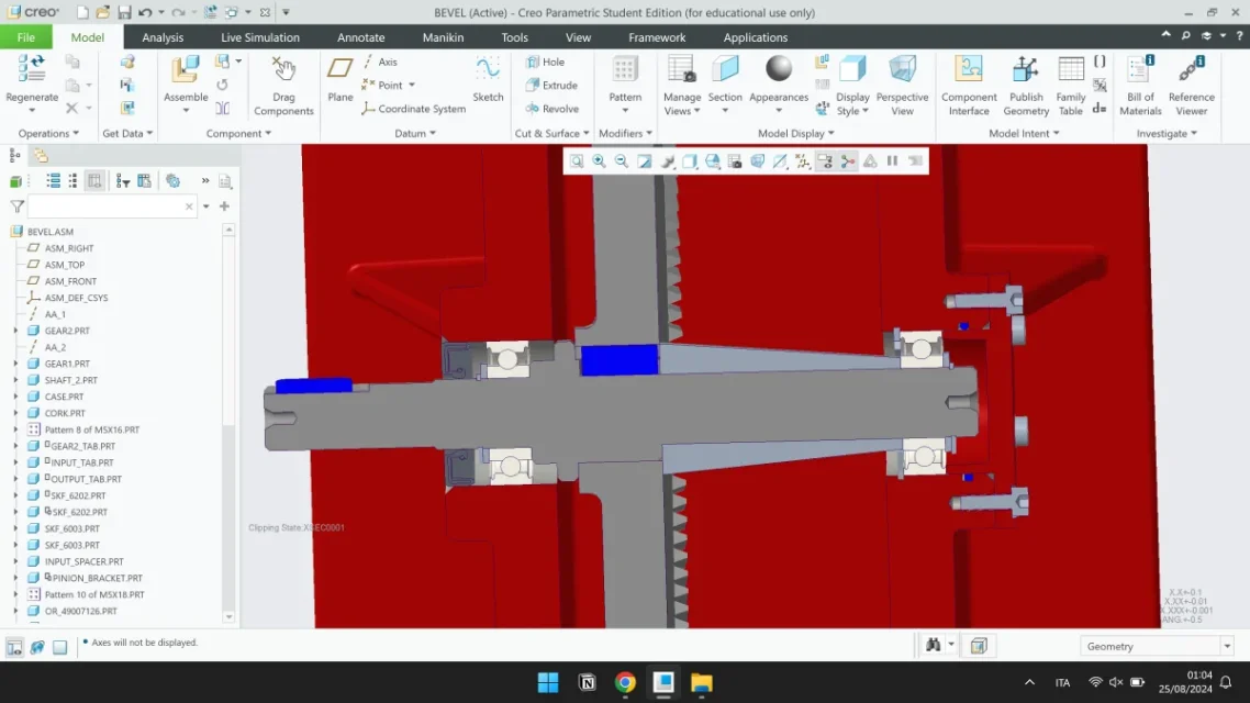
conductor: 17 teeth, dn 25.5mm, delta 5,71°
conduct: 170 teeth, dn 255mm, delta 84,29°
I chose radial ball bearings as they respect loads (I checked on skfbearingselect.com):
-conductor skf 6202
-conduct skf 6003
I attach the cad section I've made, do you have advice on how to improve it?
Thank you.
I am facing the design of an angle reference at 90° with 1 pair of straight tooth conical wheels, of which I know:
- engine power: 0.55 kw
-Input number: 1380
- Couple. 3,81 nm
-transmission ratio: 10
- Yield: 0,95
- working hours: 16
-type of load: lightweight
- useful life: 50,000 hours
from the calculations I got:
conductor: 17 teeth, dn 25.5mm, delta 5,71°
conduct: 170 teeth, dn 255mm, delta 84,29°
I chose radial ball bearings as they respect loads (I checked on skfbearingselect.com):
-conductor skf 6202
-conduct skf 6003
I attach the cad section I've made, do you have advice on how to improve it?
Thank you.
Attachments

Last edited:
.webp")