np426
Guest
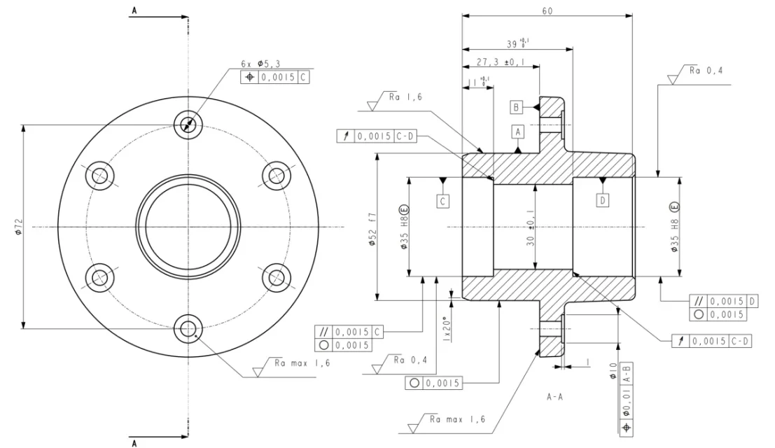
I was doubtful, for the thickness of registration of the pinion I thought of using This is so as to facilitate registration, alternatively as suggested by mechanicsmg was to do it from full to then rectify it.
In both cases, removing material can only advance to the right... In case the recording should be in the opposite direction, how do I fix it? should I take it for example of 4mm (what I did in the cad is 3mm) so as to have a discard to be able to use in case of need?
In both cases, removing material can only advance to the right... In case the recording should be in the opposite direction, how do I fix it? should I take it for example of 4mm (what I did in the cad is 3mm) so as to have a discard to be able to use in case of need?