
You are using an out of date browser. It may not display this or other websites correctly.
You should upgrade or use an alternative browser.
You should upgrade or use an alternative browser.
Mike1967
Guest
but, I looked at it, but it seems a little messed up, first of all the thicknesses are not regular.according to you can convert this particular sheet metal for development and cutting? sincerely I tried for little and only my curiosity.
Thank you.
I don't think the propeller can be turned into sheet metal.
PiegatoreSolidworks
Guest
we say that I drew it as if it was a fried piece only to convert it into sheet metal, but in reality I do it from a plate 20x4 in copper. .but, I looked at it, but it seems a little messed up, first of all the thicknesses are not regular.
I don't think the propeller can be turned into sheet metal.
sampom
Guest
more than convert it you can try to do it directly in sheet, with the loft:we say that I drew it as if it was a fried piece only to convert it into sheet metal, but in reality I do it from a plate 20x4 in copper. .
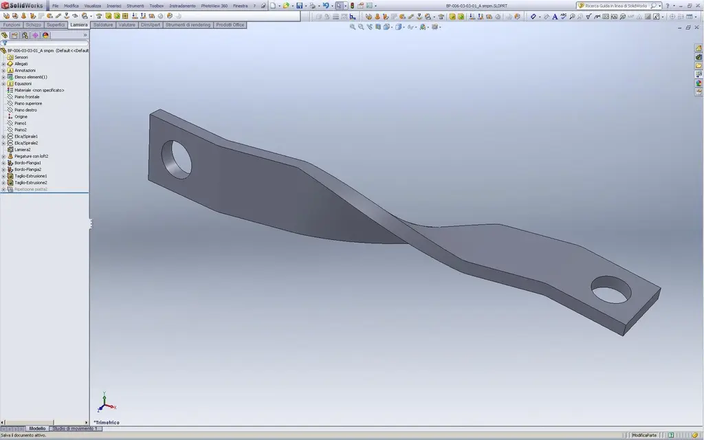
qui il file: View attachment BP-006-03-03-01_A smpm.rarthe thing works, but development may be a little unlikely even if somehow feasible.
greetings
Marco:smile:
PiegatoreSolidworks
Guest
thanks sampom, definitely a great solution even if I didn't understand much of propellers....adesso I look at the guide and try to do it...practically the loft you do it between 2 props?more than convert it you can try to do it directly in sheet, with the loft:View attachment 22253
qui il file: View attachment 22252the thing works, but development may be a little unlikely even if somehow feasible.
greetings
Marco:smile:
sampom
Guest
Yes. between the 2 3d sketches obtained from the propellers. Can you see the file? Try to inspect the "retrose" tree, it is simple as modeling, you should understand well....practically the loft you do it between 2 propellers?
with that system we get some "pseudo developments" for the screws, look:
greetings
Mar
Attachments
PiegatoreSolidworks
Guest
I've never seen anything like that! But then how do you realize it? What kind of "calandra" do you use? I'm curious. .Yes. between the 2 3d sketches obtained from the propellers. Can you see the file? Try to inspect the "retrose" tree, it is simple as modeling, you should understand well.
with that system we get some "pseudo developments" for the screws, look:
greetings
Mar
and the pseudo development is okay or you have to correct it?
sampom
Guest
I was talking about "pseudo" development:biggrin:. with the cad representation do what you want, the realization then is another pair of sleeves.But then how do you realize it? What kind of "calandra" do you use? I'm curious. .
and the pseudo development is okay or you have to correct it?
However, those are not made of calandra (not in the narrow sense of the communes); who makes coclee starts from a "piatto" (a little like your copper foil) that is "around" around a round soul (a bar or a tube) through a kind of lathe and properly guided.. (there are some videos on youtube, try to search).
only that the size of the resulting section will no longer be the original ones. for "striction" you have that the dish will be thinner and lower (usually. but depending on the method used may also be higher).. the difficulty in predicting this change of size is the problem that is in the process of design/design; you have to tell the operator which bar to take to get some result. but who does that job has enough experience to know "memory" how to operate. a little like for the plates, you have to audit the machine, detect and report the data on the cad.
greetings
Marco:smile:
sampom
Guest
here you see a series of proceedings:http://www.youtube.com/watch?v=tuofgtcajno&feature=relatedAs you see, they are much more diversified than I said before (I know only about it. I use and mute often coclee from sheet metal tape, but I make them do and buy them.. I see they build them a little as I want.
Last edited:
PiegatoreSolidworks
Guest
thank you for the Moroccan drittas, this topic is very curious to me! after I deepen. . .here you see a series of proceedings:http://www.youtube.com/watch?v=tuofgtcajno&feature=relatedAs you see, they are much more diversified than I said before (I know only about it. I use and mute often coclee from sheet metal tape, but I make them do and buy them.. I see they build them a little as I want.