• This forum is the machine-generated translation of www.cad3d.it/forum1 - the Italian design community. Several terms are not translated correctly.

assembly sheet in inventor: rabbit

  • Thread starter Thread starter rosariomartino
  • Start date Start date

rosariomartino

Guest
hello to everyone, I'm at first with inventor and I would like to ask you a suggestion.
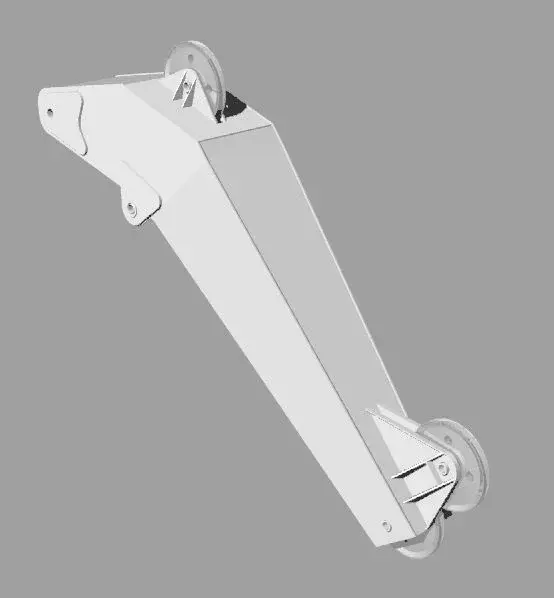
for work, a few years ago, I made a crane with rhinoceros. Now I'd like to try and rebuild it in the inventor but I can't figure out which way to follow. the crane consists of a boxed (see example image) made of sheet of various thickness welded between them. I can't understand if I have to make the single sheets and then assemble them with complacent constraints or if I have to use the welding environment. I would be grateful if someone could give me suggestions and/or references to learn.
Thank you in advance. . .
 

Attachments

  • jib1.webp
    jib1.webp
    7.2 KB · Views: 20
I can't understand if I have to make the single sheets and then assemble them with constraints

sì.
or if I have to use the welding environment
the difference between the joint environment and the welding environment is in the possibility to insert welding and preliminary or mechanical processing.
in the welding environment you can make rough welded and then work it as on a ut machine.
I personally prefer to do the work on the individual components, I find that it is more governmental during the recovery of the semi-finished products, in the face of an increase in the number of components. (equal plates with different holes are one in the case of mechanical processing, n. in case of preparation of individual machining on each piece ).

Bye.
 
a technique that I like and creates very "robust" models in case of variations are those that in English are indicated as "skeletal modeling" and "muscular modeling" (the first uses sketches, the second solids), a search with google makes you jump out various things. dictated in pennies:
1) you create a "skeleton" part that schematically represents your final set;
2) create various derivative parts that use this skeleton
3) use the points, axes, skeleton surfaces to create your components;
4) in your final set, the skeleton is fixed at the origin and all other components are bound to the origin plans of the skeleton.

In this way, when changing the skeleton, all parts adapt (variations not too "radical")

in the past I have seen videos on youtube showing everything in practice, I should also find some examples.
 

Forum statistics

Threads
44,997
Messages
339,767
Members
4
Latest member
ibt

Members online

No members online now.
Back
Top