
• This forum is the machine-generated translation of www.cad3d.it/forum1 - the Italian design community. Several terms are not translated correctly.

base flange with sweep

  • Thread starter Thread starter tanticapelli
  • Start date Start date

tanticapelli

Guest
Hello, everyone!

I have a problem: I would like to make a c-tube consisting of a folded sheet that will have to serve as a bond to a dot of a tilted roof of 17 ° regarding the horizontal. the dot will be a 180x60x5 boxer.

I'm trying to use the "basic flux with sweep" function.

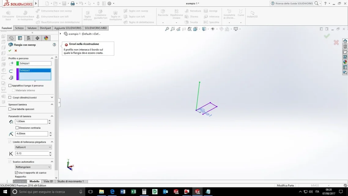
in the example that place I used sketch1 as flange profile and with sketch3 the trajectory to follow.

sketch2 served me to create the tilted auxiliary plan of 17th compared to the upper floor.

I also tried many other times without creating the usiliary plan without results.

when I launch the function of "basic flunge with sweep" and do sketch1 as profile "to extrude" and sketch3 as trajectory the program responds as follows: "herroris in reconstruction: the profile does not intersect the edge on which the flange should be created".

How can I do that?

And yet I don't feel like doing something different from this video: https://youtu.be/n1-t4h1gghqThank you!

so many hairs
 

Attachments

  • esempio 1.rar
    esempio 1.rar
    31.3 KB · Views: 4
  • esempio1.webp
    esempio1.webp
    72.6 KB · Views: 8
profile and path must be perpendicular.
instead of starting from a tilted plane do the sheet perpendicular to the path and make a cut of 17th next
 
profile and path must be perpendicular.
instead of starting from a tilted plane do the sheet perpendicular to the path and make a cut of 17th next
Well, I wanted to avoid having an extruded cut.

So now I understand.

Thanks massive!
 
Hello again...

I tried to practice an extruded cut after flattening the sheet, but how much I replenish the extruded cut is lost and besides some functions go between them in conflict.

you could kindly describe the correct procedure to get the shape that I want both in flattened mode (which will have to keep the characteristics even in the design that I will create) and when it is folded (which is the way in which I will insert it together).

Thanks again

so many hairs
 

Attachments

Hello again...

I tried to practice an extruded cut after flattening the sheet, but how much I replenish the extruded cut is lost and besides some functions go between them in conflict.

you could kindly describe the correct procedure to get the shape that I want both in flattened mode (which will have to keep the characteristics even in the design that I will create) and when it is folded (which is the way in which I will insert it together).

Thanks again

so many hairs
I reached the sheet I wanted.

but now when I create the design and tell him to see me with "flat repetition" it does not flatten me!!! !

It's not possible... .
 

Attachments

because the flat repetition is active in the default configuration and suspended in the default development. must be reversed.
or even better delete the default development configuration and recreate it by inserting the view into the drawing environment.
to make the cut all that manphrine did not need, it was enough to make a normal cut extruded by quotating the final result of the sheet.
two functions and had done everything
 
because the flat repetition is active in the default configuration and suspended in the default development. must be reversed.
or even better delete the default development configuration and recreate it by inserting the view into the drawing environment.
to make the cut all that manphrine did not need, it was enough to make a normal cut extruded by quotating the final result of the sheet.
two functions and had done everything
ok thanks for the advice on how best to organize the extruded cut!

I managed to set the design with the flat repetition that works as... flat repetition.

but I don't understand what I'm wrong because every time I have to delete the "default development" configuration in the part file and let it create the drawing file when I insert a view with flat repetition.

is also correct to change a sheet using these steps?
1) create "c" sketch (in this case) and create a simple basic flange;
2) use the "distendi" function to be able to draw the necessary sketch for extruded cutting;
3) extruded cut;
4) fold function;

after which my solid has the characteristics I want.

5) design creation from the side;
6) insert suitable view with flat repetition;
7) flat repetition is not flat;
8) back to the part file and in the configurations section eliminate the "default development"
9) I once again generate the design and insert the view with flat repetition finally works (with the appropriate automatic bending notes);

Am I wrong?

Massivonweizen is it possible to exchange a contact in case of need since you are so good?

so many hairs
 

Forum statistics

Threads
44,997
Messages
339,767
Members
4
Latest member
ibt

Members online

No members online now.
Back
Top