• This forum is the machine-generated translation of www.cad3d.it/forum1 - the Italian design community. Several terms are not translated correctly.

basic table view bound to multibody axle system

  • Thread starter Thread starter Alby189
  • Start date Start date

Alby189

Guest
hello to all, I would need help with regard to the table views with reference to system of axes in part multibody. use catia v5-6r2016 with license cac+mce+mme.
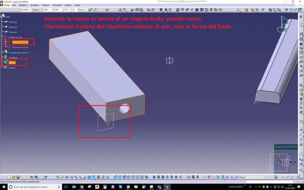
I often work in multimody in part environment, I tried to insert axis systems on the faces of the individual leotards to have a parameterized reference for placing on the table, then I put on the table the individual leotards using as a orientation plan the systems of axes previously inserted.
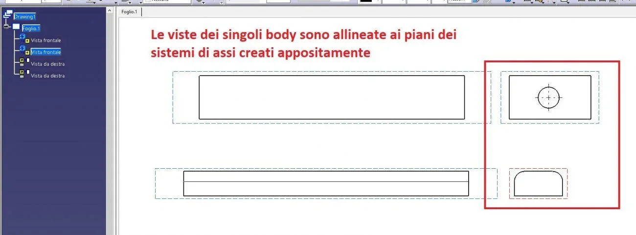
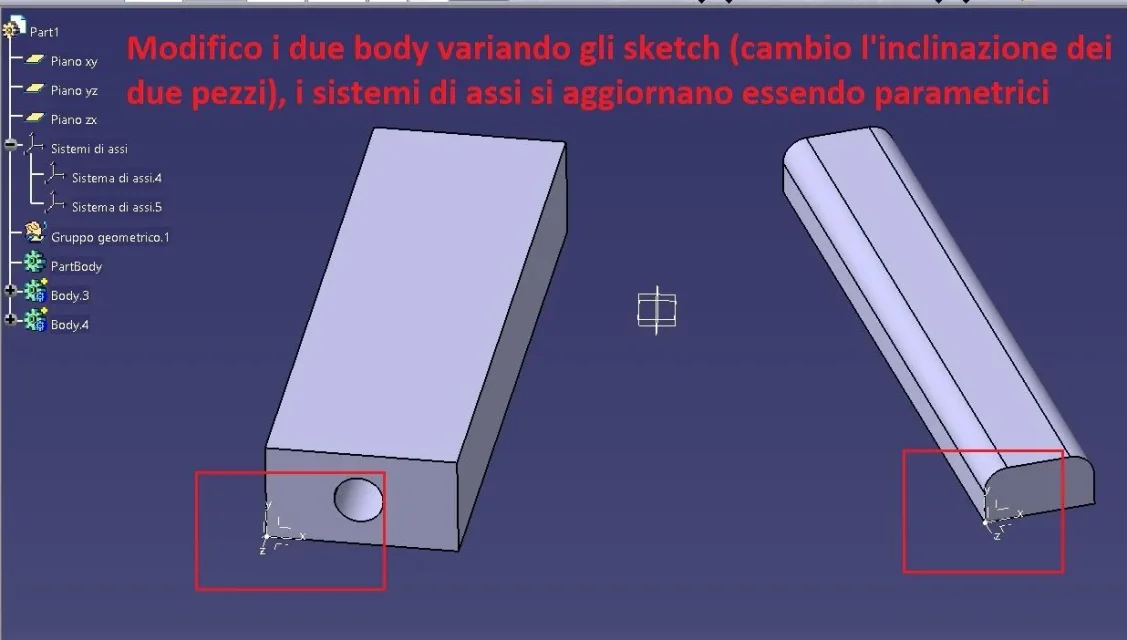
modifying the body, the respective axles are updated being parametric, but updating the table, the basic view is deformed and does not follow the system of axes previously selected during the creation of the view, I thought using as reference the axle system the views were updated accordingly.
Is there a way to get that result? that the basic views of the individual body remain bound to a specific plan of the part?
I attach some pictures to explain myself better
Thank you all!
 

Attachments

  • 1.webp
    1.webp
    41.3 KB · Views: 11
  • 2.webp
    2.webp
    67.8 KB · Views: 11
  • 3.webp
    3.webp
    33.6 KB · Views: 9
  • 4.webp
    4.webp
    52.3 KB · Views: 9
  • 5.webp
    5.webp
    46.1 KB · Views: 15
Hi.
Are you sure you have selected the plan of the axis when creating the view?

try to create a floor on the surface and use this as a reference.

Let us know. Okay?
 
thanks to the answer, yes, I was very careful in selecting the plan generated by the system axes. Moreover I tried also with a plan, the result is always the same, the basic view in the table is not bound to the plan/system sits in the part and loses the alignments. . .

a solution I would have found myself is very long:
- copy the body to put on the table and the respective system of axes to it bound
- in a new part paste with connection (body and system axes)
- create a new axle system in origin
- move the body with reference from axis to axis (from the one copied to the one in origin), at this stage the body aligns itself to the origin of the new part and remains bound
- put on the table the new part with the body copied (and connected to the original multibody)
in this way any modification to the original multibody is repercussions in the new part and the body always aligns itself to the origin, therefore in the table you do not disalline

Unfortunately, however, I cannot adopt this procedure because of a huge amount of drawings to be managed for this project and I must remain with the multibody part without being able to generate other parts with links.

thanks for the attention
 
try to change strategy.

first place in space the axle system for a body.
then create or move the solid (body) by leaning on the plane of the axle system you created previously.

Let me know.
 
I just tried, unfortunately it does not even work with the proposed approach, I first created the system of axes and various planes, then I built on the solids, once put in the table with reference the same systems of axes, do not bind to the base view.. .
I don't know how to do it, and if it's possible... .
 
Okay thank you, I'll attach three files with which I did the tests:

- multibody.catpart part: this is the multibody native file
- derived.catpart: this is a part file where I glued with reference a body with respective axle system, then I created a new axle system in the origin, and I moved the axis body to axis; in this way to every modification of the primary body, the mathematics here updates but does not change origin and orientation
- draging1. catdraying: there are views of both files (specified inside), modifying the body of the native file and updating all files you can see how the views react.

Unfortunately, in this specific project I cannot manage everything with the second working option, so I should find, if possible, a solution to bind the basic view to a specific plan so that it is updated with the changing of the body.
thanks again for the help! !
 

Attachments

Hi.
I did a quick test with your examples but with a new design.

I confirm you have the same problem with v5 r30 sp01.

bypass: Once you change the angle in 3d, go into the drawing on the properties of the view with the right button and change the projection plan.

That's how it works.

but I think it's anomaly...
 
Here's the option I told you.
as said behaviour does not seem correct.
But at least you have a solution.
Okay?
 

Attachments

  • BE60C432-96FB-4D6E-A2DF-AD83A846A97D.webp
    BE60C432-96FB-4D6E-A2DF-AD83A846A97D.webp
    79 KB · Views: 15
Clearly, I know that command, I already use it to overcome the problem, but it is several hundred views to redefine the basic plan, I was looking for a solution to make it automatic.
in practice I have a set with dozens of parts all in multibody and boards of all details; then with "new from" pointing the file with the boards all new and I modify some parameters of the geometries to get a new set with parts resized with the new specifications, all for at least twenty versions, in this way in a very short time I also have the updated tables, but in this case I will continue to review the plans of each single view.. .
Thanks anyway for the time you dedicated me! You were very kind!
 
Okay, I know what you want to do.
it would seem (use the conditional) that catia takes account only of the original plans.

I never had a problem in many years of work.

I think about it and see if with the help of some colleagues I find the solution.
maybe there is an option to set....

If I have any news, will I let you know?
 
Hi.
I fear that falonef is right: catia defines the generated view plan and it is possible to change it only with the command "modification projection plan". . .

I did a test with the option "view from 3d" setting front views/ annotation plan and indeed if in the options imposed "synchronizes during the update", the view updates, but its projections no, unless you select them and each time give the command "synchronizes the definition of the view" for each projection, but we are again there: it is not practical.

I also tried to create a product where I fixed a blank part and compared to that I align all parts through the tarts, so they actually align, but then you have to manage the updates according to the selections and in the case of the multibody with an additional set of lighters and turns off.

perhaps acting on the formulas where the plan of view generated must be replaced by the corresponding plan of the terna but that ground for me is unknown.

Hi.

years ago
 
Hi I tried to remake tests with v5 r28.

But analyzing the behavior of the software I see that if you activate the view, the original terna > blue arrows is shown which correspond to the original terna in the catpart.

I therefore deduce that despite having selected the new terna in 3d, after the update you find yourself with the view moved into space.

I tried to create a hole and create a view in the auxiliary section.
This also moves, so another clue to my previous conclusion.

I can't find a solution.
 

Attachments

  • sketcher.webp
    sketcher.webp
    54 KB · Views: 12
I did a test with the option "view from 3d" setting front views/ annotation plan and indeed if in the options imposed "synchronizes during the update", the view updates, but its projections no, unless you select them and each time give the command "synchronizes the definition of the view" for each projection, but we are again there: it is not practical.
thanks for the info, could you tell me how the command "view from 3d" works? I never managed to use it and even after several attempts I understood how it works, unfortunately in the company colleagues are not very hard and I am self-taught. . .
Thank you!
 
Hi I tried to remake tests with v5 r28.

But analyzing the behavior of the software I see that if you activate the view, the original terna > blue arrows is shown which correspond to the original terna in the catpart.

I therefore deduce that despite having selected the new terna in 3d, after the update you find yourself with the view moved into space.

I tried to create a hole and create a view in the auxiliary section.
This also moves, so another clue to my previous conclusion.

I can't find a solution.
thanks again for the attempts!
 
I don't know.

to use the view from 3d, you must first create all views (or sections) in the 3d of the catpart, this method allows you to insert all information such as quotations, geometric tolerances and notes, directly in the 3d so wishing you could avoid putting into the table always that the workshop can use the format.

in case you want to use the views in the drawing:

menu/iser/view/projects/view from 3d

and selection of the view created in the catpart, so you will get the properly filtered view of its only contents

to create them in the catpart, in generative design environment:

menus/insert/viste-plates of annotation/front view and selections a floor, flat surface or axle system.

in your case you could create many front views and sections to share your body and get the views you need.

you have to go to the menu/instruments/options/mechanical design/drafting/view/view from 3d/ check mark on synchronized during the update.

Unfortunately to insert more complete quotas and tolerances, you must have the functional chesting module annotation.

Do some evidence and let me know.

Hi.


years agoCapture_002.webpCapture_004.webp
 
Thank you so much for the detailed explanation, I will do some tests, I did not know this functionality.
I hope in company they make us do courses.... catia has many functions that by self-taught are difficult to find, after 6 years of use I am still learning!
 
for the functional toleracing annotation module you have to buy the license.

what gianni55 explained above corresponds to the 3d-master philosophy.
looking in the various forums you will find discussions created by de.
Good reading?
 

Forum statistics

Threads
44,997
Messages
339,767
Members
4
Latest member
ibt

Members online

No members online now.
Back
Top