• This forum is the machine-generated translation of www.cad3d.it/forum1 - the Italian design community. Several terms are not translated correctly.

calculation circle reinforcement tank filled with liquid

  • Thread starter Thread starter Giancesa
  • Start date Start date

Giancesa

Guest
Hello, everyone.
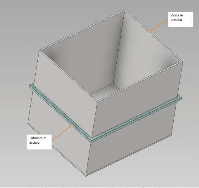
I am not expert in dimensional calculations and I have to dimension a steel "circulation" that aims to contain the deformations of a tank (I must decide whether to make it in steel or plastic) filled with water.
I would like to use the fem calculation of inventor and then apply a f load on the circle, but I did not understand what formulas to use to determine the hydrostatic pressure and its position.I do not know if the argument has already been treated.precisely I am very rusty on hydrostatic calculations, so I ask you if please someone can just bring me some formulas. Thank you very much.
 

Attachments

  • vasca+cerchiatura.webp
    vasca+cerchiatura.webp
    29.2 KB · Views: 30
Hi.

First of all the pressure of your tank is distributed evenly on the walls of your tub. Is it a pressure tank? Is it just atmospheric pressure? However once the pressure on your walls is established, I will reduce it in the section of your wrapping and do the checks of the case...
 
the pressure exerted by the liquid is the sum of two components.

the first component is the atmospheric pressure that insists on the free surface of the liquid and is transmitted unchanged to all surfaces that the liquid reaches. in the case of the container you designed, this pressure is balanced by atmospheric pressure on the outer walls of the tub and therefore can be overlooked in order to calculate what you want to do.

the second component is the hydrostatic pressure that varies linearly from the share of the free fur (no pressure) to the bottom, where the pressure is maximum. for water, the pressure can be approximately 10 kpa per meter of depth from the surface.

to simulate the tank full of liquid, you must apply a variable pressure from zero to the maximum above, to the four inner walls of the tub, linearly distributed from the share of the free fur to the bottom.
 
a reservoir with open roof and filled with a liquid will exercise on the container two types of thrust:
- thrust on the bottom as a weight of the uniform liquid on the surface of the bottom, similar to an orthogonal reaction to the bottom itself
- side push on each wall, triangular pressure with zero value to the free and maximum fur on the bottom, assimilable to a horizontal reaction placed at 1/3 height from the bottomIMG_20190610_225015.webpso it goes from itself that the circle will be useful to place it in the center of thrust of the wall....no more up and no more down.

ro that is density, worth 997 kg/m3 for water under standard conditions....simplified in 1000kg/m3 with good approximation.
 
so it goes from itself that the circle will be useful to place it in the center of thrust of the wall....no more up and no more down.
is not true: it depends on the shape and structure of the tank. in those drawn, the upper part is subject to greater deformation due to the lack of the equivalent to the bottom. in this case the circle, if unique, should be placed much higher.
 
to tell the truth a circle should be made immediately up and one to 1/3 of the height....this as long as the tank supports on an indeformable surface ...otherwise it closes all on itself...and the bottom sinks.
then at industrial level they put 3 or 4 of bands on plastic tanks.... more for aesthetics than for real function.
You still do a fem and you'll see where you'll need to put the reinforcement band.
 
I saw doing something like that using a metal cage that as it went down it fits.
in my case it was a deep well about 10 m.
the section, being a well, was circular.
 
I think it started with a bit of confusion and then this went up. . .

First, it must be clear that a "circulation" does not carry out the task required. in the barrels, or in the circular containers, the circles serve to prevent the breakage of the traction containers of the building material (or the separation of the slats in the case of the barrels).

in the case of parallelepiped containers, the external reinforcement serves to prevent the deformation of the container which, considering a horizontal section of the tank/cisterne, without them would lead to the visible in the following figure.
Cisterna.webpif the reinforcement you want to use is a thin band (similar to the barrel circle), its contribution will be practically null, and the deformation will remain unchanged. to obtain the result sought, a cage with its structural rigidity is necessary to oppose the deformation indicated above.
Actually, a circle should be done right up and 1/3 of the height. .
also this is wrong: that value "1/3", has nothing to do with the position of the reinforcement element.

If we imagine a vertical section of a closed tank (such as those of trade, of type "coated"), the behavior at the stress of hydrostatic pressure can be approximated with the study of a bending beam subject to load distributed as in the following figure.
Trave.webpthe linearly distributed load (the full tank is supposed), the position of the resulting of the distributed force (the famous "1/3" above) and the position of the maximum arrow.

solving the differential equation that represents the curve assumed by the beam under effort and equating the derivative before such equation to zero to find the minimum point, you get the value reported in figure that (as easily intuitable) is very close to the half-carry.

in the case of the closed container, the best height for reinforcement is the tank halfway, in the case of the open tank, the two reinforcements should be at the highest point and still at the halfway.
... this as long as the reservoir stands on an indeformable surface ...otherwise it closes everything on itself...and the bottom sinks.
It is worth pointing out that if the lower part of the walls of the tank does not yield when the same rests on a flat surface, neither would the bottom "blood" because subject to the same pressure and the material to the sex tension. Actually, the deformation of the reservoir could lead to an increase of the piezometric height of the liquid fur and resulting increase of pressure at the bottom, but it could also happen the opposite if the "split" of the walls led to a decrease. in the case of a suspended structure, everything would depend on the suspension points and the direction of the applied forces.
then at industrial level they put 3 or 4 of bands on plastic tanks.... more for aesthetics than for real function.
This is a very personal interpretation. aesthetics in an industrial tank plays a fairly marginal role, not to mention null. multiple circles, connected to each other, as in the figure below
Serbatoio.webpto give structural rigidity to the cage for the above reasons.
 
a very simple concept, without disturbing too many scientific calculations, since the load is distributed triangular is to counter the resulting note placed at 1/3 with a rigid metal structure that supports this reaction. if the reinforcement leads to zero the reaction, you will not have the bending to 0,45*l, so it is better to act where there is the reaction, rather than in "half" where there is still to calculate the real force that is discharged at that point.

then everyone is free to proceed as he best believes, on the origin of force or on the consequence of deformation as long as they get the prefixed result.

of the reservoir above the second horizontal crossing starting from above serves only to hold the rectangular plate of the label, not sure to hold the deformation of the reservoir. water, oil, fuel, nothing will deform the first 400mm up... simply symmetry and aesthetics, not structural need. It seems obvious.
 
my obvious pair.
on this there is no doubt, but only on this.

of the rest, it has already written about the uselessness of mathematics, calculations... rational mechanics only serves to waste time, also because then... it's all so obvious! :

If you're spending some time in the middle of your evidence, take a look here.
http://www.itimarconi.ct.it/sezioni...costruzioni/linea elastica/linea elastica.htmIt's high school math, nothing impossible for a mechanical engineer. maybe apply the simple formula
image227.gifto the case in question. He thinks they get the same results I got... cases of life.
 
Last edited by a moderator:
Maybe you interpreted otherwise what I wrote. I probably have trouble communicating, so I will try again to express my concept.

if I have a phenomenon that causes a effect, in my way of acting, I try to counter the phenomenon directly and not to limit its effect.

then bringing it to the case of the tank I have:
- liquid pushes on the wall with triangular law and phenomenon is the thrust resulting placed at a third from the bottom
- the tank wall as a result of the thrust mentioned above shows a bending/deformation effect at 0,45/height from the bottom

the engineering actions to solve the problem are two:
- I put a "system" that pushes in the module equal and opposite to the resulting vector
- I put a "system" that pushes in the area where there is the maximum bending

I believe that the action-reaction system defined by the third law of mechanics is the optimal one for the resolutive approach of the problem, clean, linear, targeted and effective.
 
liquid pushes on the wall with triangular law and phenomenon is the thrust resulting placed at a third from the bottom
No, no, no, no, and no. polemic or not polemic, antipatic or non-pathetic... It's still not.

If you have a set of forces acting on a flexible system, you can't replace it with the resulting and think that the system behaves the same way.

These are so trivial things that if I try to explain it, it seems as if I took you for the melts.

I don't want to take you for the melts, but I don't even want them to pass as acceptable things that aren't.

I try: replacing a set of forces (two forces, but also a continuous distribution, as in the case in question) can be replaced by the resulting only if it acts on a rigid body!

You're an engineer, you did physics 1, this concept should be clear to you. If I invite you to go see him again, I'll call back to the direction, and then you know what? but yes, come on, we also apply the rigid body rules to flexible systems and we cheerfully cut off everything they teach in engineering.

Well, we put the band at 1/3 of the height. You're right.
I think something's wrong.
No one is sitting on the concept.
It's the way it's annoying.
Can't you argue civilly without sarcasm?
Good evening to all!

sent by my sm-a750fn using tapatalk
 
I attach you a very explanatory picture of what I technically explained above.

this is a large tank with metal walls and reinforcements arranged symmetrically at constant pace (made by this company of Neighbourhoods). was filled with a liquid with constant density and in particular water.Orizz_01-800x600.webpthe legend indicates that the effort of von mises and therefore the internal pressure generated by the fluid assumes values The Mass near the red areas and values minim in blue areas.
If you do not have discromy problems, you can see that the first third from the bottom of the wall is subject to maximum pressure due to the reaction on the horizontal bottom and reaction on the walls.
 
I only need to know if von mises is a friend of mass von wiezen.... If I'm not mistaken, they played alongside fritz walter in the national team of 54... but maybe I'm confused.
But in rome it is said: and make it over! .
peace & love all
 

Forum statistics

Threads
44,997
Messages
339,767
Members
4
Latest member
ibt

Members online

No members online now.
Back
Top