skia51
Guest
Hello everyone,
I apologize in advance if this is not the area suitable for discussion, if so, I ask the mods to move it to the appropriate area.
I have my problem.
a customer provided us a step file of an aluminum piece to work on the cnc milling.
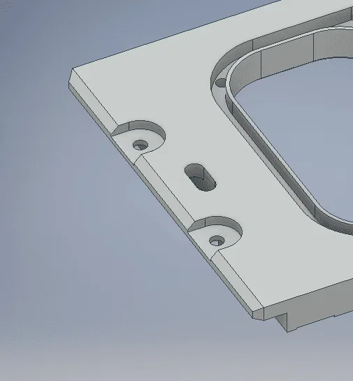
in the image you can see the beveled edge, but there are two perforated pockets that interrupt the bevel.
Moreover, there is an additional bevel in the corners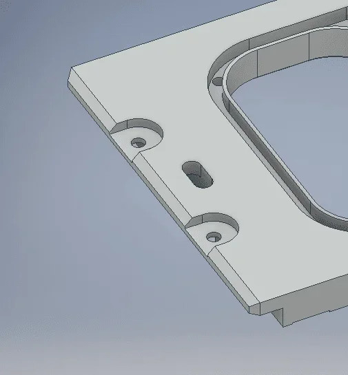 now the inventor does not allow me to fresare all the edge but to fresare three segments to carry out the bevel, moreover the attack and exit of the tool will not be on the edge but at the end of the bevel,
the tool path is visible in the second image.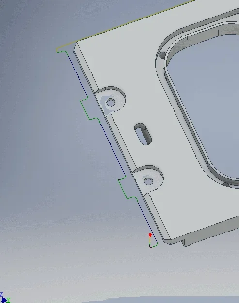 now unable to modify the 3d model, how should the operator of the cam, to have a linear tool path and not three separate cutters?
thanks to those who will help me
I apologize in advance if this is not the area suitable for discussion, if so, I ask the mods to move it to the appropriate area.
I have my problem.
a customer provided us a step file of an aluminum piece to work on the cnc milling.
in the image you can see the beveled edge, but there are two perforated pockets that interrupt the bevel.
Moreover, there is an additional bevel in the corners
now the inventor does not allow me to fresare all the edge but to fresare three segments to carry out the bevel, moreover the attack and exit of the tool will not be on the edge but at the end of the bevel,the tool path is visible in the second image.
now unable to modify the 3d model, how should the operator of the cam, to have a linear tool path and not three separate cutters?thanks to those who will help me