Leonardo26
Guest
Thank you, for your suggestions.


Hi, thank us for the suggestions, but then you don't consider them. Let's see my last straight what effect it does.Good evening again to all. I'll train you as I thought I would. the doubt that I remain is if the self-locking nut can unscrew when I lower the jack.
the bearing is axial and on one side is bare on the pin, on which I ran a pavement and on the other side I made a support that is blocked by the nut.View attachment 70810
and how do I change the manoeuvre crank? the jack that I have has a hexagonal nut drawn on the screw to which a key is mountedHi, thank us for the suggestions, but then you don't consider them. Let's see my last straight what effect it does.
the manoeuvre crank, must always be close to the jack, so it must be put in place of this self-locking nut.
then I will tell you only that both the self-locking nut and the coup will never bear the load they are subjected to: the dice turn and the brow pulls.and how do I change the manoeuvre crank? the jack that I have has a hexagonal nut drawn on the screw to which a key is mounted
the problem is that they do not sell screws of maneuver with hexagonal head and therefore I have to find another solution.
and for this I had thought of a self-locking nut but you see it wrong, but the suggestion of mechanicgm seems better
if I have not considered your advice is only for educational reasons
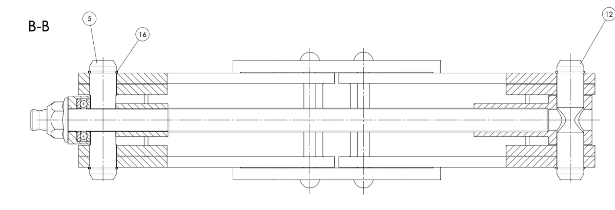
from the design it seems that the hole is smaller than the screw, but they are both from 15. Now I look at if I have wrong some setting when I did the section on solidwoks.then I will tell you only that both the self-locking nut and the coup will never bear the load they are subjected to: the dice turn and the brow pulls.
a question, how does the screw cross the pin 5, how did you draw it?
He's right. @marco f inox, the cup would be cut off almost immediately.and how do I change the manoeuvre crank? the jack that I have has a hexagonal nut drawn on the screw to which a key is mounted
the problem is that they do not sell screws of maneuver with hexagonal head and therefore I have to find another solution.
and for this I had thought of a self-locking nut but you see it wrong, but the suggestion of mechanicgm seems better
if I have not considered your advice is only for educational reasons

I forgot, once you put the crank on the milled screw, you can fix it with a self-locking nut, even if the threads are interrupted. But usually in car jacks the crank is absent and not permanently fixed for space issues.He's right. @marco f inox, the cup would be cut off almost immediately.
I would do so, I would leave the nut with cup to hold the tension.
I would then leave about 20mm of screw in addition to the nut, and on the screw I would mill two parallel planes to be able to operate it with a crank with a carving as in image:View attachment 70816
He's right. @marco f inox, the cup would be cut off almost immediately.
I would do so, I would leave the nut with cup to hold the tension.
I would then leave about 20mm of screw in addition to the nut, and on the screw I would mill two parallel planes to be able to operate it with a crank with a carving as in image:
I finally had thought of making a hole before the dice in which to insert the crank to be blocked when using with a coup, but his idea seems better to me. but instead of the dice with cup it is possible to leave the self-locking nut?He's right. @marco f inox, the cup would be cut off almost immediately.
I would do so, I would leave the nut with cup to hold the tension.
I would then leave about 20mm of screw in addition to the nut, and on the screw I would mill two parallel planes to be able to operate it with a crank with a carving as in image:View attachment 70816
I don't know, I think the autobloccnte unscrew, I'd put at least one contradado.I finally had thought of making a hole before the dice in which to insert the crank to be blocked when using with a coup, but his idea seems better to me. but instead of the dice with cup it is possible to leave the self-locking nut?
component 12 has a 17 hole. the trapeze screw is from 16 and screws on the snail and flows into the 12 pin. to left the pin 5 is not threaded. the cylendretto that contains the bearing is practically the axial support, which is blocked by the nut. the manoeuvre bar should not be fixed to the jack, also because I have constraint of encumbrance, and then I decided to do as suggested by serjo making two pavements.if you use a single threaded bar, on the right it has to screw freely in support 12 and, from the design you do not see this operation.
to the left should be removed the thread, to do the smooth coupling with support 5, but then it is no longer necessary to fill in to put dice.
It would be enough a cylinder, which also contains the bearing (this should not be paraded during the descent) fixed to the turned shaft, with a passing hole and screw.
on this cylinder you can weld the crank arm, like a folded round, or as it says @serjo, double milling of the shaft and inserting asolate arm, held firm by screw with washer on a threaded axial hole.
also here you can weld the arm to the cylinder and you avoid the thread of the head.
solutions can be different, but different design errors must also be corrected.
a banal advice. If you have a family car, open the trunk and run the jack... you'll find interesting ideas. If you have more cars and different brands, you will find different solutions.I finally had thought of making a hole before the dice in which to insert the crank to be blocked when using with a coup, but his idea seems better to me. but instead of the dice with cup it is possible to leave the self-locking nut?
 higher friction lower cost
 there are also many models cad on the net....to observe and compare with reality and make comments.