• This forum is the machine-generated translation of www.cad3d.it/forum1 - the Italian design community. Several terms are not translated correctly.

channel coupling

  • Thread starter Thread starter cal022
  • Start date Start date

cal022

Guest
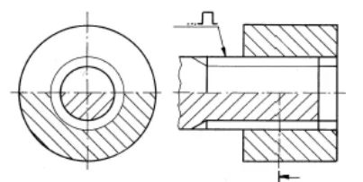
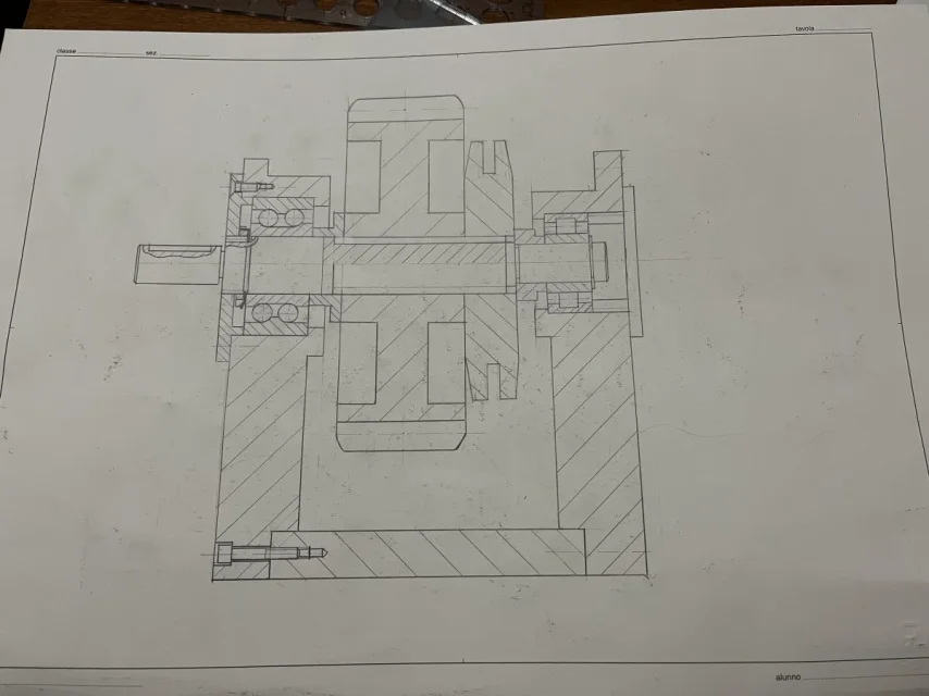
good morning, I am a student of aerospace engineering, I had a doubt about how to represent in a total, for example a transmission group of motion, a channeled coupling between a wheel and a shaft grooved, since on the internet is always found as an example the simplified representation that follows the norm one iso 6413, but I never saw it applied in a total, so I am doubted whether, dissecting the above group,
I asked many colleagues but they don't know anything about it.
I have the exam in a few days, so I would need an answer as soon as possible
Thank you.
 
trees in general do not split from top to bottom, then partial section on site and represent sampled what is full and not what is unloaded of broaching or grooved.
alternatively all dissected but half from axis up.
then they are all issues that with the fall beautifully decay because you do not draw more by hand....son different requirements.
 
Of course, the section must always be done with tear or otherwise partial, in fact it was this that did not convince me in the field totally while being in cross section, and however yes I agree, on the cad you certainly do not have these problems...
So I can use this right legislation?
 

Attachments

  • Screenshot 2024-08-25 222606.webp
    Screenshot 2024-08-25 222606.webp
    9.2 KB · Views: 35
Of course, the section must always be done with tear or otherwise partial, in fact it was this that did not convince me in the field totally while being in cross section, and however yes I agree, on the cad you certainly do not have these problems...
So I can use this right legislation?
If you don't do the edges, you can't represent anything.
But no one says you can't dissect everything.
 
If you don't do the edges, you can't represent anything.
But no one says you can't dissect everything.
I try to explain myself better.
in the image of your last post shows half view and half section for the shaft and full section for hub not because it is to be represented so but to not make two drawings did one only with the two ways to var see dissected and not what happens with the lines.
I hope I made it clear.
in my previous post I didn't even understand myself.
 
no forgive me but then it does not return to me, in theory on the right there is a complete section, and then on the left the section of the lower half of the tree on the right towards the left, but that on the right (longitudinale) should be right according to the norm...
 
shows how to represent the grooved coupling as a rule, and however the section from left to right is total, i.e. cut to half the tree and the hub, with the firmness of not sampling however the upper half because it is always an element that does not matter completely from top to bottom; and it is a total section because otherwise the upper half of the hub should not be sampled
 
that is, in this frame, in which wheel and pulley are connected through the profile to the tree, the grooved profiles represented so are all right?
 

Attachments

  • IMG_8243.webp
    IMG_8243.webp
    67.6 KB · Views: 26
following exactly the representation of post #4 should be like this:IMG_8243~2.jpegpersonally I would do without paranoid, no half dissected and half in sight but only section to tear portion of channel.IMG_8243~3.jpegno one can challenge it because the shaft is not completely dissected and if the groove has even teeth it has exactly the same blade as in my representation, with instead of the radius the 45° line of simplification.

as I don't like the simplified representations, given that to do the grooves we use the cutters ...they have a diameter and their size affects the geometry of the piece. sometimes shouldering and larger diameters close and it is good to know and represent it correctly not to find surprises.IMG_8243~4.jpeg
 
to explain why I have erased the right vertical row....the groove reaches the end of the tree otherwise you do not thread anything.
here is represented the shorter shaft of the hub because it is a representation with only one design to show everything....as with the screw threads clamping.Screenshot 2024-08-25 222606~2.pngyou probably used it to delimite the section tear but use vertical rows confuses with geometry, in fact it is recommended free-hand line fine....but at this point the end of the grooved tract coincides with the end of sampling.
 
from a drawing taken from an American book, fixed head of lathe with counterpoint, we have the particular s3 that is a tree and as such they decided not to dissect it, as the general norm dives and therefore the two grooved traits where the gears run are lined on fine-type grooved bottom.Screenshot_20240826_233951_OneDrive~2.webp
 
ok thank you very much, so the first sight would be fine except for that line at the end, which should not be put because it indicates end of the tree, and the straight line that becomes at 45 degrees (incidentally I put it straight because in other books including that mine is put just vertical), and with tear line rather than vertical line (which put so effectively has little meaning).
while the second photo you sent says it is even better because the tear is done even in the lower half (also because, according to the first photo you sent, that tear should stop in half and not continue in theory)
 
to explain why I have erased the right vertical row....the groove reaches the end of the tree otherwise you do not thread anything.
here is represented the shorter shaft of the hub because it is a representation with only one design to show everything....as with the screw threads clamping.View attachment 71929you probably used it to delimite the section tear but use vertical rows confuses with geometry, in fact it is recommended free-hand line fine....but at this point the end of the grooved tract coincides with the end of sampling.
okok, look I thank you for the clarification because unfortunately it is not explained very much on the book or on the internet on this topic, and you understand that from this representation you understand very little since behind there is no explanation...
 
okok, look I thank you for the clarification because unfortunately it is not explained very much on the book or on the internet on this topic, and you understand that from this representation you understand very little since behind there is no explanation...
in addition to screws one does not even pose the problem because beyond the mother-in-law you cannot send them, while for the channel in fact yes; the doubt however remained because this I sent you is an exercise similar to one of the exam I had done, and that, among other things, I had passed by doing the groove exactly as above
 
okok, look I thank you for the clarification because unfortunately it is not explained very much on the book or on the internet on this topic, and you understand that from this representation you understand very little since behind there is no explanation...
you are fully right and what is most bothering is that even teachers explain....poco or nothing.... of course I miss they know altrimenti otherwise they would explain it.
 
look you're perfectly right, and it's better that we don't treat the subject because otherwise I could get complaints about all the things I would like to say...
 
look you're perfectly right, and it's better that we don't treat the subject because otherwise I could get complaints about all the things I would like to say...
Maybe someone will one day realize that there is a community that tries to satisfy the deficiencies of the priests... .
 
However I did this last analysis, I also show you the hub because I’m not sure but it should go well
 

Attachments

  • IMG_8247.webp
    IMG_8247.webp
    99.6 KB · Views: 17

Forum statistics

Threads
44,997
Messages
339,767
Members
4
Latest member
ibt

Members online

No members online now.
Back
Top