• This forum is the machine-generated translation of www.cad3d.it/forum1 - the Italian design community. Several terms are not translated correctly.

check

  • Thread starter Thread starter mariom
  • Start date Start date

mariom

Guest
hello to all
I come to the problem/dubbio that happened in the department.
during the processing of some levers, they have failed to drill them, instead of performing a 50mm hole they have done it from 55mm (in the hole a tree must be inserted that feeds ) :eek:.
After having made them remake I got this doubt, leaving the experience of the case, how do I check if the lever could still be okay?
below I tell you the data of the lever, some of you can tell me what calculation or method to use for verification.
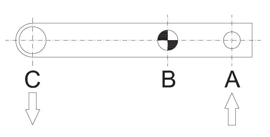
length 300mm,fitness 60mm thickness 15mm.
to be as clear as possible I attach you a sketch.
 

Attachments

  • Leva.webp
    Leva.webp
    9.7 KB · Views: 40
apart from the lack of constraints or forces (like the truth?) but, if those are forces with the bond, the leverage turns (the two forces generate a moment), that is, there is a bond of freedom!
However, the checks are done with the theory of construction science.
 
Fortunately you have attached the sketch for clarity.:smile: but what is the hole that was wrong? then the shaft was welded or simply inserted? Was this diner already built? What is the application for? to what efforts are being made? What's the problem? Does it seem right for one to help you to ask a lot of questions?
 
I did not understand where the hole was wrong.
However, once you understand the static pattern, to calculate tensions you could use the shape factors for perforated plates that, for example, are reported on the strozzi.
or, since the piece is simple, you could use the fem module of inventor, if you have it, or even on the autocad mechanical there is a fem 2d that, more unique than rare, should go well for your case.
 
but is the problem structural? or enlarged hole -> shift of the fulcrum, so is it a problem of balance?
In this case, let the de saint venant rest in peace, there is no reason to call him in question.
 
@ fulvio:
to understand, the question is quite dark and therefore I responded by interpreting.
If it were a problem of balance, I would say that enlargement does not vary the entirety but decreases the mass and then moves the mass center.
here we go on the principles of dynamics!!! ;)
 
I try to be clearer:
a : application point of the sewer (where the fork of a pneumatic cylinder is mounted).
b: fulcrum
c : hole where a bronze compass is inserted in which the cylinder shaft is placed
the cylinder pulls for a plastified paper sheet.
My problem/dubbio was if there were any problems with breaking up.
cause times and hurry I left some data I apologize....:frown:
I would like to use the fem module of inventor, but unfortunately nn I am so good and competent.
 
I would like to use the fem module of inventor, but unfortunately nn I am so good and competent.
And then you better leave it alone. a fem analysis is not something to improvise. never. it would be like to say "I would like to use a calculator, but I have not clear the difference between sum and multiplication."

In practice, I try to interpret your question, you ask: "Since the hole in which the cylinder is being drawn, it came bigger than expected, I fear that the material around the hole is no longer sufficient to maintain the load."

Right?

In that case, if you give some additional size it is easier to help you, but I would try to calculate the reduction of the resistant section, which if it makes to pack the third decimal digit (as I think) is not so much to consider. However, I do not express myself because I do not know the size of the piece.

if you say "the piece must be done again, because otherwise next time the machine operator does what ca@o wants, so much I accept the same", here, this is a sacred speech. :cool:
 
Sorry, I read the data better.
we make an easy, conservative account, that is, the account is worse than the situation, so if it goes well, if it doesn't pass you have to put yourself in a case closer to the real one.

if you apply a f force to the c shaft and the piece breaks, it will break in the horizontal section to the left. at this point the internal voltage is equal to half of the applied force divided the area of the section. this would be the case if on the right of c you had the same section regarding the left. Therefore I say that in reality the section on the right is bigger and therefore you are safer.

well, therefore, the tension is sigma = f/2a where:

a = 15*5 in the right hole
a = 15*2.5 in the case of wrong hole.

the section therefore halved, we are not talking about figures after the comma as mistakenly stated before!

However, you calculate the sigma, the divide for the admissible sigma (we do that of yielding, which for steel is about 450 mpa, but depends on the type of steel) and get the so-called "safety factor r".

If r >= 1.5, and breakage of the piece does not cause serious damage, you can feel relatively quiet.

of course, take reasoning good, but numbers must necessarily depend on a deeper knowledge of the problem
 
the fact that the durable section is reduced to half of the expected one, as it observed fulvio, in my opinion it is enough to say that the piece is no longer good.

However, I understand that mariom is not the designer: in its place I would not take the responsibility to say that a piece does not conform to the design is still well, or in any case, made due considerations, I would consult at least the designer.

if mariom wants to make a deal is a good thing, but he needs more than anything for culture and personal curiosity. in this optic can quietly put on a little bit with the inventor fem. so there are only 2-3 options and then it does everything automatically. Obviously the results then have to be taken with a very critical sense, but for what I saw on simple pieces are quite right.

in other areas I used gambit and fluent: they really cannot improvise anything, and the theoretical bases really serve, even to read the manual. the inventor's fem is quite another thing: it would be like comparing paint to the autocad.
I quote everything, except for improvising fem analysis.
by personal experience, I saw people use the cat's fem saying "it's easy, just enter the data and exit the result". then when I pointed out that changing the mesh or adding a fitting, the maximum tension changed an order of magnitude, their certainties began to falter.

I personally think that the fem serves to put the figures after the comma. to make two accounts with classical formulas serves to get an idea of resistance. Otherwise you risk really making bad mistakes, and by bad I mean really bad.
 
@marion
If you don't know the fem, you could take whistles for whistles! This is a simple problem that you can study with the science of buildings.
@fulvio
450 mpa of yielding is for a good steel but I think we will have to stay lower.
be careful that the force on the zipper is "cut" and therefore I must check the second section:
(f/b)
where:
f is the force
b*h is the base * height of the rectangle that defines the durable section.
I'll leave you linkOf course, if there's a stinging moment, I have to check out other points on the auction.
Hi.
 
I quote everything, except for improvising fem analysis.
by personal experience, I saw people use the cat's fem saying "it's easy, just enter the data and exit the result". then when I pointed out that changing the mesh or adding a fitting, the maximum tension changed an order of magnitude, their certainties began to falter.
I agree that if you have to make dimensions of objects to produce really and you do not have familiarity with the fem codes, it is not the case of using them.
I still said to use the fem with a very critical sense only for personal curiosity, not to produce a result to be included in a calculation report. for educational purposes it is interesting to deal with paper and pen, to deal with a fem, compare the results and understand why differences.

the problem is to have the right critical sense (not trivial thing). actually there is also my colleague who uses the inventor's fem lightly and takes too literally the results.
 
Why do I cut? I thought of normal effort as maximum stress...the cut would appear under the hole, but as the force is transferred from a bushing, I thought the contact pressure diagram could distribute the tensions pretty well.

450 is he a little old? I actually took it from wikipedia:-(because I'm at home and I don't have hand data, nor in mind. What value would you take?

and then the moment in the beam is not affected by a variation in diameter of the hole. If it was good before, it will be fine now, so I ignored the problem.
What do you say?
 
Why do I cut? I thought of normal effort as maximum stress...the cut would appear under the hole, but as the force is transferred from a bushing, I thought the contact pressure diagram could distribute the tensions pretty well.
is a conservative account, but which is also used.
even if the bushing distributes pressures, eventually most of the force is transferred to a fairly narrow area around the minimum resistant section. the resistant section would therefore be a little larger than the minimum, but for simplicity it takes directly the minimum one.
450 is he a little old? I actually took it from wikipedia:-(because I'm at home and I don't have hand data, nor in mind. What value would you take?
the piece is flat, therefore probably pantographed by sheet in s235/275/355. the name already indicates the yielding voltage.
 
I quote the setting chosen by lightning. personally I would suggest a verification to "refoliation" of the hole being the plastic enough (s235/275/355).

for the fem, I think that in addition to improving the approximation of the calculation, it is very useful for evaluating the local effects due to the geometry of the piece.

for example fulvio approximated the force on the left semi-section as half of the total agent on the hole. as rightly observes, the method is precautionary since on the right, there is a part to "local hardness" greater (possibly more "full") than in fact takes more than half of the load.

had, the residual thickness of the right influences this distribution and probably only with a fem you can give an estimate close to reality.

is in these cases (local effects) that I find the maximum advantage from the use of the fem.

greetings
 
I have applied your formula, but the accounts are back to me, and I can see where I am wrong, the data I used is:
f = 60n
the material is a fe410 s275
 
What? ? So much brain pool for six pounds? ? ?

Come on, I'm kidding.

I continue with my reasoning that I like most, but I do not judge wrong that done by others.

the section is 2.5*15 = 37.5mm^2. must develop a cohesion force of 60/2 = 30n. if you do 30/37.5 you have 0.8 mpa... the yield is at 275mpa.. .

a mathematician would still analyse bending, cutting, torque instability, buckling elastoplastic hinge, fatigue analysis... .

But an engineer would laugh!
 

Forum statistics

Threads
44,997
Messages
339,767
Members
4
Latest member
ibt

Members online

No members online now.
ciao
Back
Top