• This forum is the machine-generated translation of www.cad3d.it/forum1 - the Italian design community. Several terms are not translated correctly.

clarifications quote drawing

  • Thread starter Thread starter gio_deere
  • Start date Start date

gio_deere

Guest
Good evening to all and good work party,
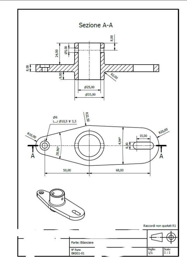
I'm a mechanical engineering student. I ask your advice regarding the quotation of his designs. I would simply like to understand if I have followed the norm well and expose a few doubts:
- in the "bilanciere" part I am not convinced whether it is right to quote the angle between the two sides or to do so compared to the horizontal
- I would like to confirm whether in both drawings the cone holes listed well (respectively laminated hole and flared)
- I would like to confirm that even the sunbeds are well listed
- any mistakes made, I am pleased if you made them notice (except for criticism)

the tables I created with inventor and in this exercise are not required dimensional tolerances (or better I asked the prof if he wanted them but has not yet given me confirmation)

I thank all those who will help me in advance!
 

Attachments

  • Immagine 2021-05-01 174915.webp
    Immagine 2021-05-01 174915.webp
    30.6 KB · Views: 115
  • Immagine 2021-05-01 174955.webp
    Immagine 2021-05-01 174955.webp
    71.1 KB · Views: 105
Hi, it seems to me that the holes and the sunshades are quoted in the correct way. with regard to the corners, I would not say a stupidity, but it is not necessary to quote them, the edges of the plate are tangent to the r10 and r20 fittings at the ends and to the concentric one to the central "tubo" of r22.5 and the interassi have already quoted them.
 
in the a-a section:
also put the cylinder diameter of the high part; for you it is obvious, but those who read it for the first time must have no doubt.
the odds of the heights aligned with each other for a cleaning of the design also put the total quota, eventually in parentheses if it is not functional) because those who have to work the particular must always have the dimensions of the encumbrance also applies to those who should prepare a shipping box)
missing the radius of the upper shoulder

in the main view:
lack the size of encumbrance (see above)
the angles I would say that do not serve the centesimal quotas and it would be appropriate to round them in the phase of modeling)
the symbols of the section are huge compared to the rest of the texts
since you have done the section use it to quote the foil is more understandable; I don't know if it's normal, and yet it's a problem for a worker.
the quotation of the asola can go well, difficult to say without knowing its function.

in general the quotas, except for particular cases such as angles, must be brought out of geometry also does not make sense to insert decimals if they are equal to ,00.
 
I didn't see the bracket...

section a-a
the position of the board on the lower side as this will be in contact with the assembly

front view:
remove 50 and place it on the side view to make the size more legible
the vertical position of the holes is worth the same speech of the asola, quote them from the base.
I repeat that it is preferable to quote them in the section.

Side view:
in this case being a l from trade it is useless to quote twice the thickness (it would be useless also to insert the radius 3.5)
the quota 50 present in the hole view
 
with regard to the corners, I would not say a stupidity, but it is not necessary to quote them, the edges of the plate are tangent to the r10 and r20 fittings at the ends and to the concentric one to the central "tubo" of r22.5 ,
only if you know how it is produced, moreover it is not said that radius 22.5 is concentric to the tube (and it seems not so)
 
[edit]other thing is that radius 20 cannot be concentric with the intersection 68.
radius 22.5 may also be concentric to the tube, but this could only be certain if there were the width of the object equal to 45.
in fact if you were to redesign this component from scratch would be impossible.
 
Last edited:
and in these cases should not extend the radius to be sure of the location of their center?
 
Thank you very much for your precious advice!
I make a moment clear, r22.5 is concentric to the "tubo". should you leave the radius and add the width 45?
for the various holes, I preferred to use the short notation to not weigh the design (also because on the text book chirone-torncasa says it is possible to make it). At this point, perhaps the laminated hole is no problem, but is it advisable to quote the diameter of the same ? or the depth ? I read a little on the forum and there is a little diatribe on this.

radius r20 is not concentric with the asola and not even with the quota 68.

However I add everything by following your advice and placed the tables. They are for an examination and are quite pointy (as right as it is) about quotation rules.

ps. @massivonweizen Looking on the forum I see you're the expert on odds, I really compliment you and I'm honored with your advice!
 
should you leave the radius and add the width 45?
as I have already written the dimensions of encumbrance must always be put, perhaps in parentheses if not functional, but are necessary for various reasons:
know the encumbrance on the machine tool
know the size of a potential raw element
know the footprint for a packaging
give input to suppliers and operators
 
er the various holes, I preferred to use the short notation to not weigh the design (also because on the text book chirone-torncasa says it is possible to make it)
I will tell you that those who work the particular do not always have studies from chirone-torncasa, rarely has dispenses in the drawer to be sprayed to see what annotations mean, rarely has the time to stop the machine to decipher a writing and can be that that that time is challenged by the production; the theory is beautiful and right, but then you collide with the practice that travels at double speed and does not make discounts.
For this reason I always say that in tolerances it is preferable to put the shocks, the gorges it is preferable to quote them instead of putting the norm, to put all the quotas and not to make calculations... .
I worked on the machines and I know what it means to go around the workshop to look for a working calculator, stop the lathe to go to the office to write the measurements of a gorge to seeger and fortunately I didn't have an extremely rigid working card
 
and in these cases should not extend the radius to be sure of the location of their center?
no, unfortunately the center of the r20 is on the axis of the asola but does not coincide with either of the two centers, for the accuracy and distant 58 from the center of the big hole, but for the purposes of the quotas is not useful (I know because of the modeling 3d)
 
I will tell you that those who work the particular do not always have studies from chirone-torncasa, rarely has dispenses in the drawer to be sprayed to see what annotations mean, rarely has the time to stop the machine to decipher a writing and can be that that that time is challenged by the production; the theory is beautiful and right, but then you collide with the practice that travels at double speed and does not make discounts.
For this reason I always say that in tolerances it is preferable to put the shocks, the gorges it is preferable to quote them instead of putting the norm, to put all the quotas and not to make calculations... .
I worked on the machines and I know what it means to go around the workshop to look for a working calculator, stop the lathe to go to the office to write the measurements of a gorge to seeger and fortunately I didn't have an extremely rigid working card
I fully understand, for my little experience in a mechanical workshop I know what it means to waste time making the accounts. Let us say that for teaching purposes my means is the return home and for normative purposes to quote the hole in that fast way is not wrong. I prefer to follow your advice and quote the holes in the classic way, surely a hypothetical operator of mu who will hypothetically receive those drawings will thank me?
I wanted to emphasize that the sunshades, expecting a workmanship with candle cutters, I felt right to quote center-centre as length.

Thank you for all the tips!
 
the speech of how and who will perform the particular is quite problematic; if you are a design office you rarely have this information, except to be a large company that makes its own products. easier than you find yourself making a generalist quotation that has to give all the information. otherwise you could, knowing that it is made with the cam, put only the control quotas
For example, you have two production roads according to the quantity to be produced:
if you have few pieces you make it welded; in practice laser cuts the 8mm plate and balance it to a 33.7x5.6 commercial tube (for example). Then we will do the processing that needs precision (the socket would be excluded because part of the laser cutting)
if you have so many pieces you make melt and do only precision processing (axle included)
It goes as if for how it is made that design do it all of fresa, starting from a rectangle full 130x45x45, it would cost an eye of the head.

this to tell you that my observations are inevitably subject to a practical vision and for purely academic purposes have a sometimes limited value. if you feel right and it is usually to quote holes with the fall caption.
 
Good morning to all, I updated the boards, I hope I did a good job.
this to tell you that my observations are inevitably subject to a practical vision and for purely academic purposes have a sometimes limited value. if you feel right and it is usually to quote holes with the fall caption.
answering them, I prefer to follow his advice also because dictated by a greater experience on the field. however as I have now listed the holes and however in standard (I hope I can confirm). for the production of these pieces, being a purely educational exercise (among other things they are also invented as pieces), the technological process has not been defined. sure as you said you get the balancer from the full coast an eye!

for the bracket: I preferred to leave the quotas of the profile to l (the thicknesses 8 and the chord 3.5) since I did not specify the profile from which it is obtained and then knowing the prof. would give it as error if I did not put both thicknesses.

Thank you again for your advice!
 

Attachments

  • Immagine 2021-05-02 094734.webp
    Immagine 2021-05-02 094734.webp
    71.4 KB · Views: 67
  • Immagine 2021-05-02 094824.webp
    Immagine 2021-05-02 094824.webp
    30.3 KB · Views: 60
I feel good. I only make a couple of purely technical observations.
in the bracket:
insert the depth of the devasation as, going to execute it, it will be easier and practical to know how much you have to descend with the devasator rather than subsequently verify diameter 12. one of the two sizes, diameter or depth, you can put it in brackets.
for a nice reading of the drawing you could move the 29 of the asola on the opposite side by aligning it to the 29 of the holes; this would allow you to take out of geometry the 10 of the width of the socket.
in the side view the axles of the asola and the holes are missing.

in the balance sheet:
on 24 and 9, in the section, aligned to 8; do not affect functionality and immediately return the understanding of size.
always in the section lack the axes of the asola
in the view in the plant turns to put the corners, perhaps in brackets and with rounded value to 29° and 5°; because you don't know how it will be produced you can't know if they are superfluous.
 
perfect I have updated everything, only one thing, in the bracket I put the boards even in the view from above even if it is hidden?1619947031996.pngI think that the balancer is doing well now.
1619947197864.webp
 

Forum statistics

Threads
44,997
Messages
339,767
Members
4
Latest member
ibt

Members online

No members online now.
Back
Top