You are using an out of date browser. It may not display this or other websites correctly.
You should upgrade or use an alternative browser.
You should upgrade or use an alternative browser.

gerod
Guest
It will be but I do not see a sheet!! !
Let us understand better. What do you want to do?
Let us understand better. What do you want to do?
zeigs
Guest
I did before doing a hand sketch, since the model still can't do it, I hope it's clear
Consider taking a sheet, cutting it as in the figure, bending it in halfway at 90° along the dotted line, then deforming it until the two curved edges match. in the "3d" I indicated with dots the ideal beginning of the curvature.
the surface is only bent, not elongated or bombed. in reality is a very trivial thing, but I can't make it in 3d
Attachments

Be_on_edge
Guest
- multiple flap with a profile to the height of your object.
- then multiple flap connected to the edge of the l with arc-shaped profile and sliding on the 2 segments of the l.
Hi.
- then multiple flap connected to the edge of the l with arc-shaped profile and sliding on the 2 segments of the l.
Hi.
zeigs
Guest
Yes, but I get a profile that looks like him, but it's not him. I mean: to do first I could draw a sketch with a straight segment and an arc, then extrude it in two perpendicular directions (at 45° from the sketch plane) and get already so what you say, but it only looks like it, it is not the sheet drawn and folded, because I do not know exactly how it becomes my curve once bent to make extrusion. or did I misunderstand what you propose?
Be_on_edge
Guest
look at this example file.Yes, but I get a profile that looks like him, but it's not him. I mean: to do first I could draw a sketch with a straight segment and an arc, then extrude it in two perpendicular directions (at 45° from the sketch plane) and get already so what you say, but it only looks like it, it is not the sheet drawn and folded, because I do not know exactly how it becomes my curve once bent to make extrusion. or did I misunderstand what you propose?
Hi.View attachment esempio 1.zip
zeigs
Guest
I get it.
But that's not exactly what I meant. with what you posted I create the model, and when they spy I get the sheet to cut and fold (which then is the typical purpose). I was trying the opposite: I have the cut sheet and want to know how it becomes bending it.
at the practical act I'm fine, just make some attempt and match the design developed to the original. However, the opposite cannot be done, because I cannot fold the sheet by binding the edges. that then is what I expected, I just wanted to be sure because my attempts were unsuccessful
Thank you.
Be_on_edge
Guest
in this case you must use the "add fold" command.I get it.
But that's not exactly what I meant. with what you posted I create the model, and when they spy I get the sheet to cut and fold (which then is the typical purpose). I was trying the opposite: I have the cut sheet and want to know how it becomes bending it.
at the practical act I'm fine, just make some attempt and match the design developed to the original. However, the opposite cannot be done, because I cannot fold the sheet by binding the edges. that then is what I expected, I just wanted to be sure because my attempts were unsuccessful
Thank you.
practical action can be convenient when you have developed and want to recreate the folds.
In fact it is much better to draw the finished piece (which is what I want to achieve at the end
") ) and to leave to the cad the calculation of the developed.
) and to leave to the cad the calculation of the developed.Here is an example View attachment esempio 2.zip
ciao
zeigs
Guest
in fact I have just developed and I wanted to make them in 3d to see the encumbrances.
Even the last one you posted is fine, in the sense that you, the fold corresponds but only because you started importing the first profile and folded it with the original fold. no longer works when the shape of the profile of the starting develop is any (the design is equivocal and seem circle arches, in fact the profile is much more complex). In that case I have to make several piege to try the best approximation. but at least now I have a starting point
Hi.
Be_on_edge
Guest
the folds I made them ex novo using the profile of the developed.in fact I have just developed and I wanted to make them in 3d to see the encumbrances.
Even the last one you posted is fine, in the sense that you, the fold corresponds but only because you started importing the first profile and folded it with the original fold. no longer works when the shape of the profile of the starting develop is any (the design is equivocal and seem circle arches, in fact the profile is much more complex). In that case I have to make several piege to try the best approximation. but at least now I have a starting point
Hi.
the shape of the cut will be that of the real and bending it you can see what you can get.
explain to me step by step what you want to do and see if it is a feasible thing, both on the cad and especially in the real world :biggrin:
Hi.
zeigs
Guest
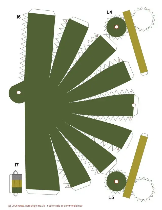
I have something like this. to not weigh down I posted only one sheet, and it is only an example. in this case the sheet is a sheet of paper, which will be cut and closed to form an object using triangular tabs. I wanted to try to make a 3d because the intention would be to do it great. Therefore it must be supported by an internal structure and, before putting them to cut cardboard or plywood or sheet, I wanted the measures (for the weight it is done early: it is exactly that of the sheet of material cut to profile!). as you can see the profiles are not simple, and consequently even when you close the shape is not a constant curvature. I don't even think she's on the same floor! even the structure itself will have special profiles, so if I can draw them all of earned: I can handle them. and to do this once I make the model 3d I love it with plans where I want to give it support and put them on the table the pieces of the structure.
ah, in this case it's a piece of marvin.. .
You know, right?
ah, in this case it's a piece of marvin.. .
You know, right?
Attachments
Be_on_edge
Guest
rest of the idea that design it in 3d and then get the developed is the best thing. especially if you have to make it big.I have something like this. to not weigh down I posted only one sheet, and it is only an example. in this case the sheet is a sheet of paper, which will be cut and closed to form an object using triangular tabs. I wanted to try to make a 3d because the intention would be to do it great. Therefore it must be supported by an internal structure and, before putting them to cut cardboard or plywood or sheet, I wanted the measures (for the weight it is done early: it is exactly that of the sheet of material cut to profile!). as you can see the profiles are not simple, and consequently even when you close the shape is not a constant curvature. I don't even think she's on the same floor! even the structure itself will have special profiles, so if I can draw them all of earned: I can handle them. and to do this once I make the model 3d I love it with plans where I want to give it support and put them on the table the pieces of the structure.
ah, in this case it's a piece of marvin.. .
You know, right?
Hi.
Marco74
Guest
quoto fully, too many variables starting from the developed to have the folded piece.rest of the idea that design it in 3d and then get the developed is the best thing. especially if you have to make it big.
Hi.
Bye.
vespa_83
Guest
How beautiful!! I like origami (I made a romboid dodecaedron by calendar); and for example origami are accurate for when they are mathematically approximate.
If you can finish qlks post any photo, I recommend!
Good luck
If you can finish qlks post any photo, I recommend!
Good luck
vespa_83
Guest
I have a problem in sheet metal:
I made the form I want to get with bluesurfing surfaces since with a loft lam I didn't get the right result.
I sewed it to make a unique surface.
how to 'convert in sheet' the surface?
"converted sheet" requires a thickened body, then with part or made "additional thickness" that in sheet metal there is not (mah!), but also so converts into sheet metal fails as there are unrolled edges and says:
--------------------------------------------------------------------------------------------------------------------------------------------------------------------------------------------------------------------------------------------------------------------------------------------------------------------------------------------------------------------------------------------------------------------------------------------------------------------------------------------------------------------------------
solid edge
--------------------------------------------------------------------------------------------------------------------------------------------------------------------------------------------------------------------------------------------------------------------------------------------------------------------------------------------------------------------------------------------------------------------------------------------------------------------------------------------------------------------------------
the model contains non-uniform material thickness or edges that must be divided.
to correct this problem:
- click on the shovel step in the command converts to sheet metal
or
- use snatch or dig commands.
--------------------------------------------------------------------------------------------------------------------------------------------------------------------------------------------------------------------------------------------------------------------------------------------------------------------------------------------------------------------------------------------------------------------------------------------------------------------------------------------------------------------------------
Okay.
--------------------------------------------------------------------------------------------------------------------------------------------------------------------------------------------------------------------------------------------------------------------------------------------------------------------------------------------------------------------------------------------------------------------------------------------------------------------------------------------------------------------------------
Attachments

Marco74
Guest
always in par you have to reach the living edges, then turn it into sheet metal.I have a problem in sheet metal:
I made the form I want to get with bluesurfing surfaces since with a loft lam I didn't get the right result.
I sewed it to make a unique surface.
how to 'convert in sheet' the surface?
"converted sheet" requires a thickened body, then with part or made "additional thickness" that in sheet metal there is not (mah!), but also so converts into sheet metal fails as there are unrolled edges and says:
--------------------------------------------------------------------------------------------------------------------------------------------------------------------------------------------------------------------------------------------------------------------------------------------------------------------------------------------------------------------------------------------------------------------------------------------------------------------------------------------------------------------------------
solid edge
--------------------------------------------------------------------------------------------------------------------------------------------------------------------------------------------------------------------------------------------------------------------------------------------------------------------------------------------------------------------------------------------------------------------------------------------------------------------------------------------------------------------------------
the model contains non-uniform material thickness or edges that must be divided.
to correct this problem:
- click on the shovel step in the command converts to sheet metal
or
- use snatch or dig commands.
--------------------------------------------------------------------------------------------------------------------------------------------------------------------------------------------------------------------------------------------------------------------------------------------------------------------------------------------------------------------------------------------------------------------------------------------------------------------------------------------------------------------------------
Okay.
--------------------------------------------------------------------------------------------------------------------------------------------------------------------------------------------------------------------------------------------------------------------------------------------------------------------------------------------------------------------------------------------------------------------------------------------------------------------------------------------------------------------------------
Bye.
vespa_83
Guest
always in par you have to reach the living edges, then turn it into sheet metal.
 then I leave it so, so the supplier arranges with his programs.
zeigs
Guest
Kids: Unfortunately now I am too instigated with the carnival to put them to paste pieces of paper for personal dialect. As soon as I get rid of myself and try, but I suspect I have to use a Zen patience at the last power.
By the way: if you think that you create curved surfaces and sew them with if sometimes it is frustrating, think about doing so by bending mdf panels and "cucirli" with schedines. Then you will understand what frustration is:4404:. .
By the way: if you think that you create curved surfaces and sew them with if sometimes it is frustrating, think about doing so by bending mdf panels and "cucirli" with schedines. Then you will understand what frustration is:4404:. .