
• This forum is the machine-generated translation of www.cad3d.it/forum1 - the Italian design community. Several terms are not translated correctly.

constraints in holes made on sheet metal

  • Thread starter Thread starter Saviolirn
  • Start date Start date

Saviolirn

Guest
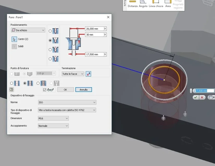
hi guys, I'm ale, I tried to look for the previous posts but I didn't find anything, I explain to you what my problem is, I use inventor 2012, after creating a sheet metal using flange contour , I go to create holes on the curve part (Ray 500mm) , up here I found very useful the forum, when I go to assemble the assemblies and I want to constrain the above holes. How are you doing? help me vade my mental health. for now thank you very much:
 
for the system (cd) those are not holes, there is no perpendicular plan to the axis but a curved surface.
you can make a small lamatura, but it would be a false processing, or use a combination of other constraints.
 
thanks stefanobruno, to a small lamatura I had not thought, but I have many holes in that sheet and would like to build a flat tangent sheet for each single hole! for the combination of constraints instead what do you suggest? I've been trying for a while but I'm high sea
 
Sorry I couldn't send the answer
Anyway
I use this technique:
- I create a plan with the inclination I need
- sketch on the newly created plane and create a circumference
- surface extrusion to intersect the sheet
- I create an axis with the newly created surface and also want a point
- with command divides select the surface and a sheet face
- with command I remove the face
with this method I get a perfectly round hole on a sheet metal very faithful to reality is important the selection of the face (internal or external)
alternatively use the command explains and folds depends on what you want to get
Hi.
 

Forum statistics

Threads
44,997
Messages
339,767
Members
4
Latest member
ibt

Members online

No members online now.
Back
Top