• This forum is the machine-generated translation of www.cad3d.it/forum1 - the Italian design community. Several terms are not translated correctly.

convert parts to components

  • Thread starter Thread starter RiccDS
  • Start date Start date

RiccDS

Guest
Hello, beginner questions for me.

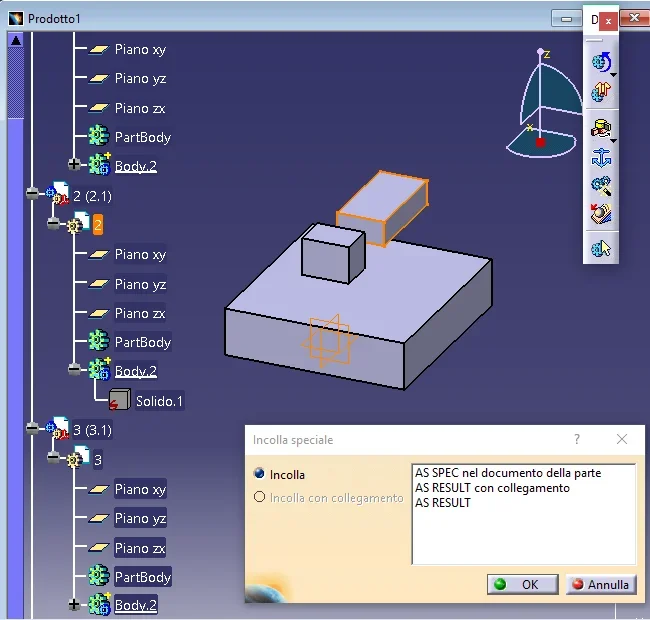
I have an open project with not a few parts. I would like to convert all these parts into components so as to manage them under a product; What is the fastest way to do that? at the time of the realization of the model unfortunately I did not save the parts as components in separate files.

Thank you.
 
Hello Ric,

You need to clarify the terms.. .

in catia the "parts" are single files (the catpart files) and are manageable in a product (the catproduct file).

if you want to group them into a component, i.e. a "virtual product" that is visible and manageable in a product but does not generate any files, you do not have to make any transformation, create the component and use it to group the parts.

the fact that you say you didn't save the parts as components in separate files what exactly does that mean?

Hi.

years ago
 
Hello, thank you.
You're right. I was wrong with terminology. I wanted to say: in part design I created a part composed of various body(s) without worrying about drawing them separately and without saving the individual body as parts. I did so because I had a better view of the body complex, and also to decide the relative measurements between the body it was easier than to undo between various file parts to take the measurements.

to which I wanted to introduce joints and then animate the mechanism. I then moved to dmu kinematics but here I can't insert joints (e.g. a rotation joint) between two body of the same part. from here the need to convert individual body into parts. I was wondering if there is a faster way to save a body as a part without having to, for example:
1- tone in part design
2- eliminate all other body
3- save the part
4- go back to history (which I find is not possible once you have saved)
5- repeat the same operation for all other body

I certainly miss a few logical pieces because it seems natural to have a workbench in which I can draw a part having to click the others.
 
Hello Ric,

Okay, you've been working on multi leotards and you want to save more parts. .

Maybe there are faster ways, but I'm in the mountains without PC and I don't think of anything else.

You can do this:

create a product
create many parts as they serve (for the empty moment)
open multi body
close the two windows
select the first body you need and copy it
go to the other window, select the first blank part and paste special as result
lathes in multi body
select the second body and copy it
go to the other window, select the second blank part and paste special as result
etc. until you are finished and save the product with all parts (to which you have put the constraints)

the multi body preserves it original and parametric for any changes
the product uses it for cinematics
if you need to change something, go back to paste copy
 
it really works thank you; with two open caty instances (I tried so because otherwise I can't work in dual screen) the program crashes to attempt to make paste copy from one to another. but in a single instance with two open windows you succeed, with the sin that so I can not go in dual screen. the only thing, when I do special glue of the feature or body(it works in both ways), for example a pad object, in fact I do not come as result as you said, but it appears as specified in the part document. There are no alternatives of choice. Maybe it depends on the version.

I have a doubt, working in this way remain relationships between files? i.e. between the bodies in the multibody file and the parts in the product file? or become completely independent?

One last thing: so if I liked from the beginning to work in this way to define my work objects, i.e. having under eye all the other parts, I would want to create a product from scratch, then add the parts(new part), double click on the single part to enter the environment part design and draw there. Right?
 
Hi.

Yes, of course, one instance.

dual screen is not necessary, just use side (windows) vertically.

do not select features (you can but serve for other purposes) but select the body at the top and copy it with ctrl+c

if select pad does not give as result just because it is a feature, then paste it as specified in the document, I repeat, copy/select the body or the gear at the top and when incolli in the new part selects the beginning of the tree and not the body generated by default.

do not "have" to stay connected (use conditional as they are not there with you to check your settings) for security made the copy post the tree so that I can see the symbols and understand if they are related.

Yes, next time, create a product, insert new part, double click on the part and enter part design... if you have too many parts, long shaft and you confuse, select the part, dx key opened in a new window and see/lavour only on that part then if you want to check how the design is stacked with the other parts, view or close the product window.

In principle it is better to do:

each separate detail, i.e. that you assemble and mount = one cappart each

each particular compound of several objects that will eventually be soldered among themselves, such as a frame consisting of different tubes, a support with welded/repealed nuts etc. = a catpart designed in multi body
 
I read a little about the difference between partbody and body. In general, wouldn't it be worth gluing in the partbody instead of letting me create a new body? from what I read there would be some features of the program that require a body that is fed to him both of partbody type, that is the default object, otherwise they do not work.

attached there is the product space of a test file since I worked on the original and the tree could no longer reflect the operations you suggested. on the left you see the body glued as you suggested. at the bottom right the options that gives me when I paste special. I did a further test and when I use "as result with connection" in the tree there is a cube with a green ball compared to the case predicted "as result" in which the cube is with a red s. I believe I have found answer to doubt :rolleyes:

the other indications are very useful.
 

Attachments

  • Catia_copy.webp
    Catia_copy.webp
    36.8 KB · Views: 10
Hi.

Yes, I confirm that green ball = link

it is confirmed that red lightning = explicit/sparameterized/not connected.

Yes, I confirm that for boolean operations and some downstream applications (type analysis or cnc) it may be appropriate to use the partbody.. .

partbody hierarchy is easily solved:

select the body, right click, body object, partbody change, a window alerts you to repositioning in the hierarchy (from ok), the body will become the partbody, at this point the body (empty that was partbody) deletes it and you will get what you need.
 
perfect gianni, it also works this passage even if I have to say some descriptions of commands in catia (it will be the Italian version) seem a little counterintuitive.
Thank you very much for taking the time to answer.

Bye-bye.
 
I said soon and in fact... I have a new inherent problem that while looking around I couldn't solve.
when I do paste as result with link (useful to change the same bodies in a blow), the copied bodies are represented with the green ball, or, I read around, with a blue dart in case the copy is made within the same part. the problem that I don't solve is that with the green ball I can't move the copies in space, that is, the shifts but when I do the update return to the position of the original body. Does anyone know if you can solve it?
 
Okay, nothing I think I've solved. a chi servisse, right click on the object linkato-> add location. then apply a transformation feature of the translation type, rotation etc.
 
when I do paste as result with link (useful to change in a shot the same bodies) the problem that I do not solve is that with the green pole I can not move the copies in the space, that is the move but when I do the update return to the position of the original body
If when the shifts return to the original position, it is because you did not do as I told you, that is to open a window with the multibody and another with the product and the new blank parts. . .

you probably did everything in one product and the system connects them more "rigidly" (chain symbol). .

if the body is the same, there must be no more catpart with different names that contain the same body in different position, but in the product you have to copy the same catpart as you need and then move them with the constraints
 
Okay, nothing I think I've solved. a chi servisse, right click on the object linkato-> add location. then apply a transformation feature of the translation type, rotation etc.
as I have already written before, if the body is the same, you have to insert more occasions in the same product and use the constraints, do not move with transformation features.

rather sends some image showing geometries and tree
 
If when the shifts return to the original position, it is because you did not do as I told you, that is to open a window with the multibody and another with the product and the new blank parts. . .

you probably did everything in one product and the system connects them more "rigidly" (chain symbol). .

if the body is the same, there must be no more catpart with different names that contain the same body in different position, but in the product you have to copy the same catpart as you need and then move them with the constraints
no in this case I started a new product from scratch to practice a little bit and I created the bodies only after entering new blank parts in the product ( insert-> new part and then double click on the gear of the new body to draw it). Then I tried to copy the bodies, that is, the gear, on one side to another empty but obviously, as you say, the copy is more rigid, even if I do not see symbols of chains. I see the green ball as known in the first screenshot. are those rectangles to the side that I want to connect to only one of them. so if I decide to change his measurements just as I do it to one.
if the body is the same, there must be no more catpart with different names that contain the same body in different position, but in the product you have to copy the same catpart as you need and then move them with the constraints
I tried to do as you say and it actually works this time. see second screenshot. In fact, it is much better because as long as I change one randomly between those created. I miss the reason to copy them with links as previously done if then one cannot move copies if not Moroccanly with the features of transformations. But so much, so many things escape me.
 

Attachments

  • fold.webp
    fold.webp
    36.8 KB · Views: 13
  • fold2.webp
    fold2.webp
    59.8 KB · Views: 12
the chain is there and is seen in the first image under the green gear of part6 and part7.. .

working in the product using the links, you enter the context design field, the rules are multiple, the slightly ostical descriptions and the slides are tricky, if you want to do exercise better starting from simple things, use the online guide and its examples.

a description of what you want to do and something will come out.
 

Forum statistics

Threads
44,997
Messages
339,767
Members
4
Latest member
ibt

Members online

No members online now.
ciao
Back
Top