
• This forum is the machine-generated translation of www.cad3d.it/forum1 - the Italian design community. Several terms are not translated correctly.

coordinates in tube axis

  • Thread starter Thread starter meacmae
  • Start date Start date

meacmae

Guest
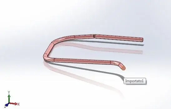
good morning, I would like to ask if there is the possibility to extract the coordinates in format (x,y,z) of a tube with various folds as from attached image.
I better explain, I have to reproduce this element with bending machine that needs x,y,z coordinates of each fold point (the intersection point of the two central axes of the tube. (then she thinks how much to bend and rotate the head).
I hope I've been clear, but I'll ask you.
Thank you.
 

Attachments

  • 1.webp
    1.webp
    9.5 KB · Views: 58
good morning, I would like to ask if there is the possibility to extract the coordinates in format (x,y,z) of a tube with various folds as from attached image.
I better explain, I have to reproduce this element with bending machine that needs x,y,z coordinates of each fold point (the intersection point of the two central axes of the tube. (then she thinks how much to bend and rotate the head).
I hope I've been clear, but I'll ask you.
Thank you.
try to attach the file, however I think you can do with 3d sketch...
 
I also believe that it is feasible by exploiting the provisional axes, which are created in every Kurdish element, and points. with a 3d sketch should be enough to give the intersection bond between two axles and a point to get the position in the fold point space
 
years ago I found myself facing your own problem,
having to extract the coordinates of hundreds of pipes it became heavy.
I had found a macro for sw that still works (sw2012)
Pretty good.
I tried to find her, but she seems to have disappeared from the network.
I'll coach you.
this leans on excell and creates a table with the points you go as you select (starting obviously from 0.0.0.).
this according to me is very convenient for piping as the macros that are around you extract all points in the sketch and then you have to filter only the intersections that affect

greetings
pier
 

Attachments

Thanks what I was looking for.
but how do you use it? I'm throwing the macro and then?
 
Hi.
If you don't have to combine with the excel file, you can also go to the 3d of the tube, and activate the command displays sketches. At this point click on the intersection of the two axes and at the bottom right you will have the xyz coordinates, so doing for all the curves you will have as much as you ask
Hi.
 
Hi.
until the sw2010 the mask remained in the foreground.
I also noticed that on 2012 the mask is opened but remains under the window of solidworks, so you have to reduce sw and keep the mask side by side.
how it works is simple enough:
select a point and clikki add, at this point the macro should open excell and start compiling coordinates, do so for each point and then exit.
the compiled table is placed directly in sw ( zoom ext).
if you do not compile anything could depend on how the excell sheet name is set (the macro is written for sheets in Italian) "sheet 1" rather than "sheet 1" .
However it is always possible to change it.

greetings
pier
 
Thanks, guys.
I now have a new problem because the file that passes me and that I open in sw and igs and my tube should extract the centers of the curvatures (the intersections of the neutral axes) only that the file maybe is made with other cad and therefore nn I have the solid elements but of the "I believe surfaces".
are imported objects cannot be transformed into extruded solid elements in order to find the intersections of the axes?
 
Hi.

you can try to make a sketch3d and bind the concentric lines to the right traits of the tube (think functions also with the surfaces).
their intersection coincides with the neutral axis at a bend radius=0
greetings
 
I can't tie you a file, if it could be addressed you would be fantastic.
I would need x,y,z coordinates compared to the reference system I put at the beginning of the tube.
 

Attachments

I'm sorry, but with a tube shaped like that, I just can't help you.
apart from the origin of the model that does not match 0.0.0. and that you could solve by entering a new coordinate system.
the biggest problem is that the curves are not on defined planes, as you would expect for a pipe, but they are simil-spirali.
This is why you do not find any intersection of the neutral axis.

greetings
 
the only one that comes to mind:
on the attached file I created a 3d sketch, which, however, at the intersection of the axes has minimal lines (less than 0.2 mm), which correspond to the error that is in the construction of the curves.
Now you can, with the measured command set on the new coordinates, have the x,y,z points, .

greetings
 

Attachments

Oh, my God, if you want to do a 3d sketch from scratch, I suggest you read the help.
However, the lines on the straight sections of the pipe must bind them "concentric" to the tube itself, then add a segment that connects them near the curve, and make it as short as possible.

greetings
 
No not from the beginning, I do the concentric lines to the straight tubes, ok but to make the union segment I do not know on what plane to do. If I prolong these axes they intersect but do not join.
 
the segment you do not have to do it on a plane but directly in the 3d sketch by joining the axes,
then the quoti and, at attempts, you can give it a minimum dimension without hypervincing the sketch.
you can also try, before listing, to put a "perpendicular" bond
to an axis.

Do you keep in mind that these are approximations, with which the tube was modeled?
 
With what program I don't know, I'm being spent in .igs and the amount.
precision, fine, having to bend the tube with bending machine, precision is mm.
So what you did is okay.
beautiful would be a macro to extract x,y,z, knots of 3d sketch but for me impossible to achieve.
 
It is impossible for me to achieve such a macro.
what I attached to you, unfortunately it refers to the default coordinates, and that's why the tubes always start them from 0.0.0.
There might be a solution to be able to use it on these tubes, but it is a bit laborious:
Make a new part.
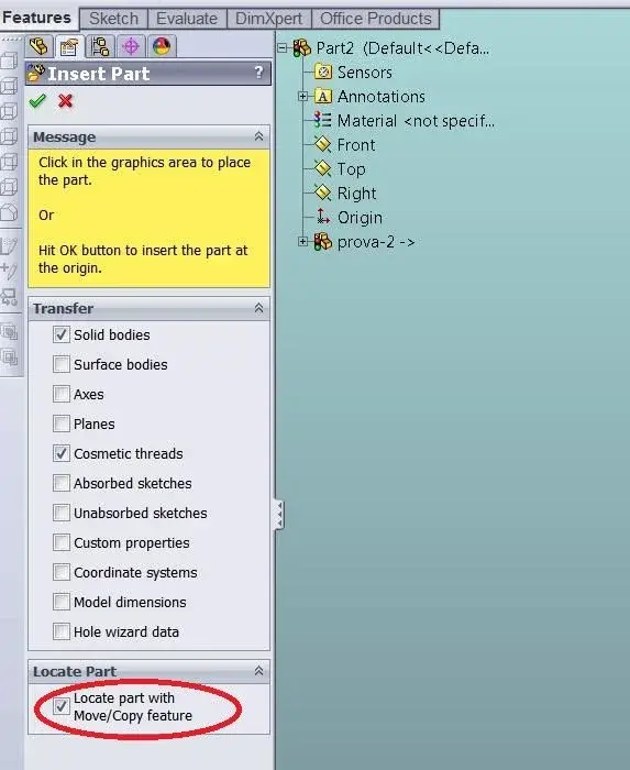
insert the tube already converted into sw.(menu :insert>part)
active the baffet locate part (see screenshot)
Now you can add the constraints to place the tube on the origin of the new part.
at this point you still have to do 3d sketch etcc. etcc. but with the advantage that will depart from 0.0.0.

Now you can use the macro.

Hi.
 

Attachments

  • ScreenShot001.webp
    ScreenShot001.webp
    37.4 KB · Views: 12

Forum statistics

Threads
44,997
Messages
339,767
Members
4
Latest member
ibt

Members online

No members online now.
Back
Top