• This forum is the machine-generated translation of www.cad3d.it/forum1 - the Italian design community. Several terms are not translated correctly.

create hand rest for scale consolid edge st

  • Thread starter Thread starter Cervantes90
  • Start date Start date

Cervantes90

Guest
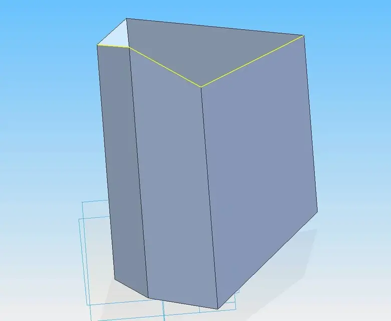
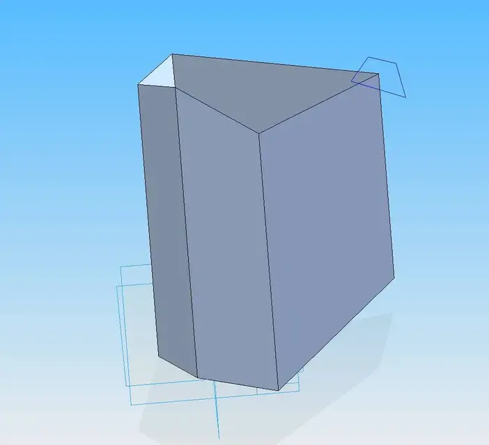
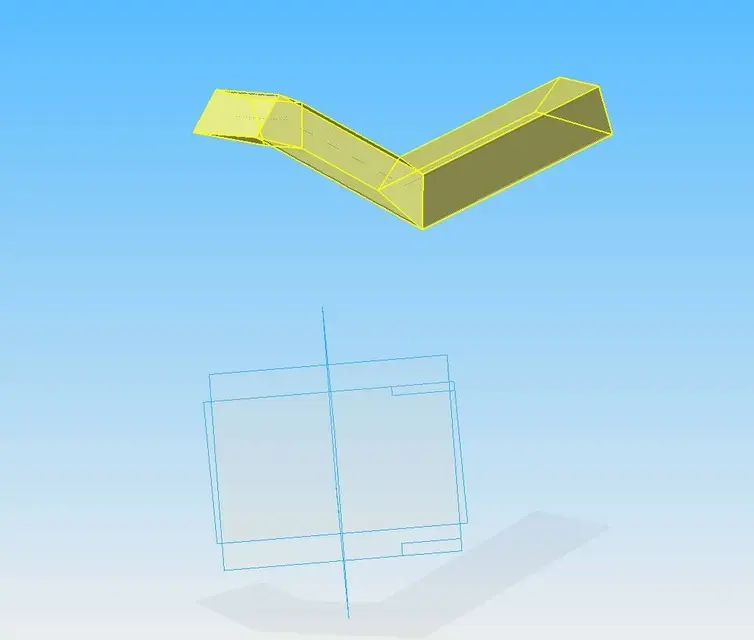
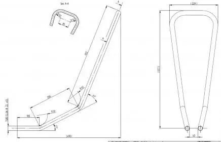
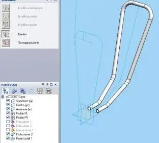
hi are cervantes90 work in the sheet metal field with solid edge, I have a problem I have to create a round hand rest with a particular shape, to do this I used the scroll function but nothing to do. the problem is that the path is formed by 3 lines which are found in different planes, perpendicular to each other and with different angles. How can I do that?
 

Attachments

  • Immagine.webp
    Immagine.webp
    106.2 KB · Views: 30
hi are cervantes90 work in the sheet metal field with solid edge, I have a problem I have to create a round hand rest with a particular shape, to do this I used the scroll function but nothing to do. the problem is that the path is formed by 3 lines which are found in different planes, perpendicular to each other and with different angles. How can I do that?
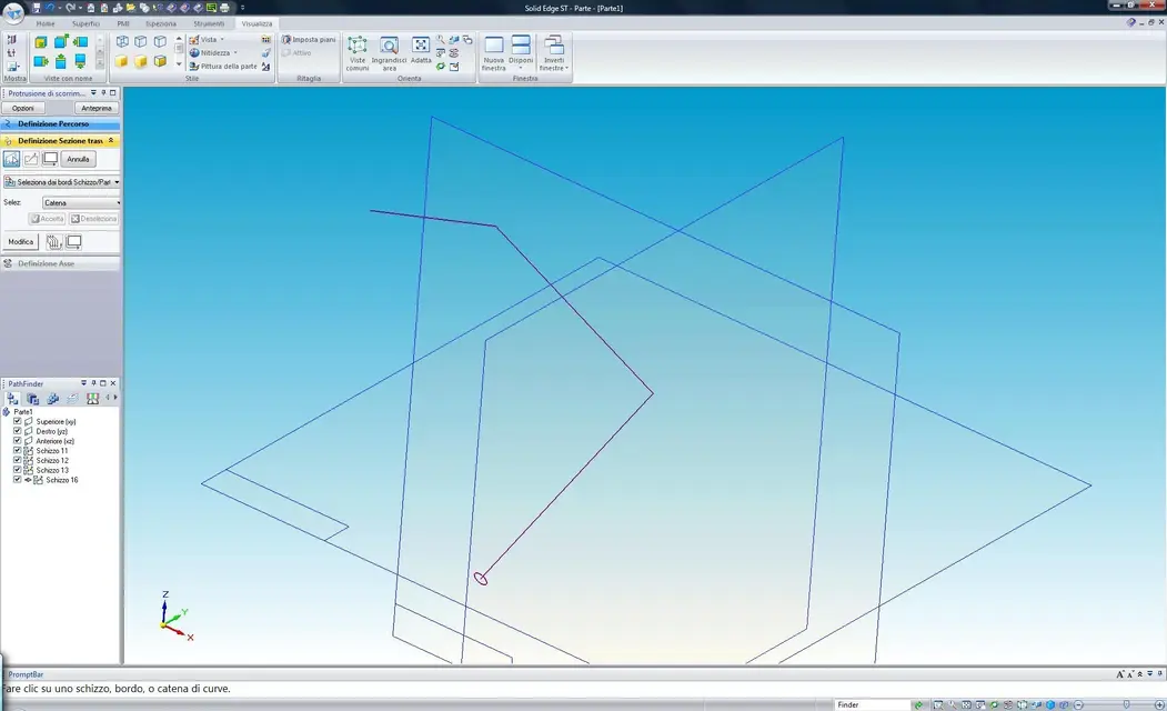
then posting the file, from the image I can't quite understand what you have to do and why if it doesn't. Do you use st or st2?
hello and welcome
 
In fact, I understood very little!
a simpler sketch than that of the se?
Maybe on cheese paper?
Hello and welcome
 
I realized what you have to do, you have created sketches by defining the normal plan at the curve, so your sketch is as oriented in space and not on a plane.

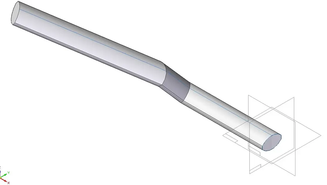
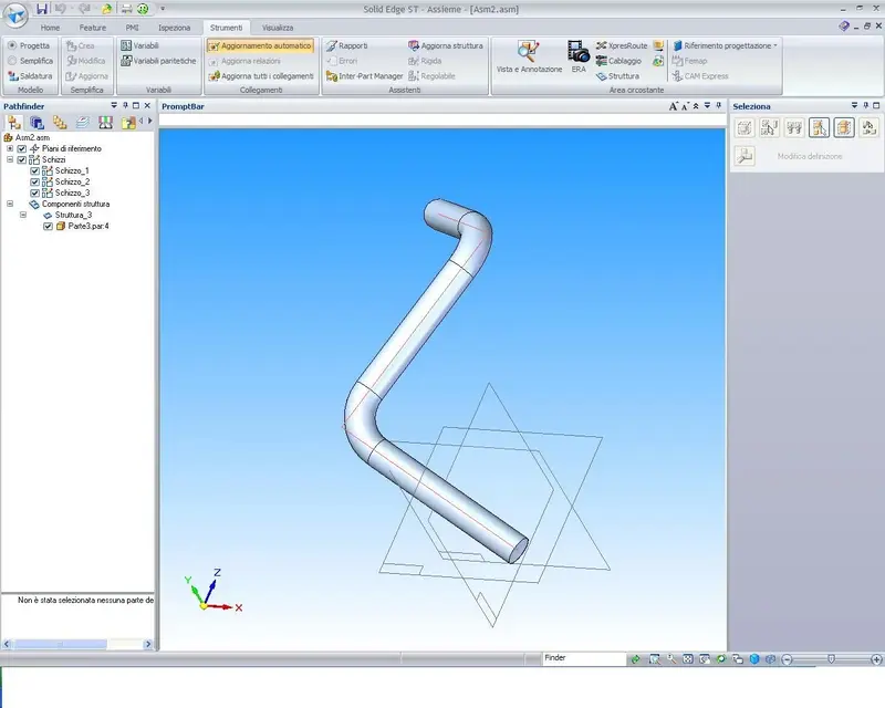
with the protrusion command of sliding not even to me creates the path, the loophole I found but doing the sketch in assembly in the same way that you did it in part. I created a cylinder and in the environment structures I made it flow by putting on the options of the structures the tick on applied radius so it creates the path.

Surely it won't be what you need but for now it's the only way. if someone else succeeds in the environment please indicate the correct procedure that interests me.

Hi.
 

Attachments

  • percorso.webp
    percorso.webp
    72.6 KB · Views: 24
....
if someone else succeeds in the environment please indicate the correct procedure that interests me.
Hi.
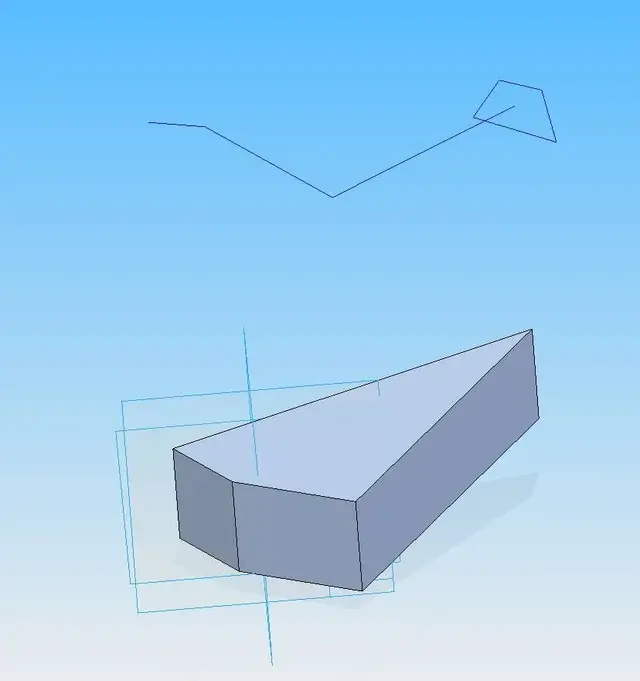
I found a procedure to get a space-oriented break-guide, in part environment, to be used as a guide for sliding protrusion, it is absolutely elegant but it works:

1- create a solid that has a chain that matches the desired guide, and on that chain use the “derive curve” command.
2- create the sketch (flat perp. a curve) of the cross section.
3- partially dig the solid, so leave the sketch alone.
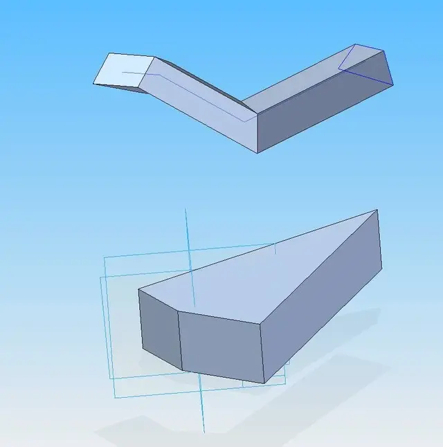
4- perform the protrusion of scorr.
5- dig the remaining part of the building solid, leaving only the protrusion obtained.

If someone finds a more "Christian" method, it also affects me.

to all
 

Attachments

  • 01.webp
    01.webp
    19.3 KB · Views: 4
  • 02.webp
    02.webp
    18.7 KB · Views: 4
  • 03.webp
    03.webp
    19.6 KB · Views: 5
  • 04.webp
    04.webp
    26.7 KB · Views: 4
  • 05.webp
    05.webp
    23.1 KB · Views: 4
You guys don't have to go invent such complex procedures. what the user has to do is to join the parts of the sketches in a single curve. there is a special command, not as it is called on the st but on the v20 it is called derivative curve.

ciao
 
You guys don't have to go invent such complex procedures. what the user has to do is to join the parts of the sketches in a single curve. there is a special command, not as it is called on the st but on the v20 it is called derivative curve.

ciao
true, but the problem, at least for me, is how to get randomly oriented cuves in the space to be derived.
 
I found a procedure to get a space-oriented break-guide, in part environment, to be used as a guide for sliding protrusion, it is absolutely elegant but it works:


Good morning
I was about to post my contribution but you preceded me
Hello everyone
 

Attachments

  • Cattura.webp
    Cattura.webp
    36.9 KB · Views: 14
You guys don't have to go invent such complex procedures. what the user has to do is to join the parts of the sketches in a single curve. there is a special command, not as it is called on the st but on the v20 it is called derivative curve.

ciao
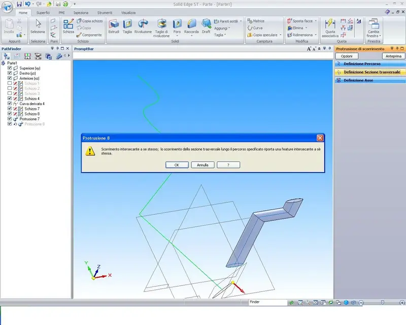
on the st2 is located on the surface menu and is called "derivata", but once created if I use the protrusion command does not hear it and it gives me error, so we are from head again. If I have to add connections between the sketches unions I don't know how to do, since the mistake says it intersects itself.

How do you do that? Thank you.
 

Attachments

  • scor1.webp
    scor1.webp
    88.4 KB · Views: 16
You guys don't have to go invent such complex procedures. what the user has to do is to join the parts of the sketches in a single curve. there is a special command, not as it is called on the st but on the v20 it is called derivative curve.

ciao
I tried to run with drift curve and image place.
- scrap on xy
- Skull on yz
- derived curve
- I'm on a normal plane at the curve.

Could you tell me if that's how you meant to create your hand rest?
thanks and greetings
 

Attachments

  • Cattura.webp
    Cattura.webp
    3.1 KB · Views: 8
on the st2 is located on the surface menu and is called "derivata", but once created if I use the protrusion command does not hear it and it gives me error, so we are from head again. If I have to add connections between the sketches unions I don't know how to do, since the mistake says it intersects itself.

How do you do that? Thank you.
You understand what I want to do! I had also tried the drift, but it makes me the same mistake. I wanted to do it with the par file. instead with the sheet metal file and then switch to par to create it and then develop it but nothing. I think the problem is the fact that you cannot add the fittings. Sorry I don't express myself very well because I'm foreign. thanks cmq for all the answers you are giving.
 
I tried to run with drift curve and image place.
- scrap on xy
- Skull on yz
- derived curve
- I'm on a normal plane at the curve.

Could you tell me if that's how you meant to create your hand rest?
thanks and greetings
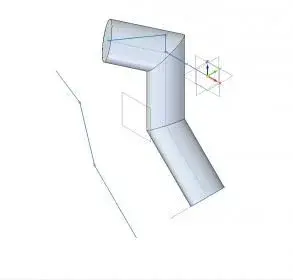
but as you see there are no fittings
 
You understand what I want to do! I had also tried the drift, but it makes me the same mistake. I wanted to do it with the par file. instead with the sheet metal file and then switch to par to create it and then develop it but nothing. I think the problem is the fact that you cannot add the fittings. Sorry I don't express myself very well because I'm foreign. thanks cmq for all the answers you are giving.
the underlying problem is that if you do not manage the sketches in the space in a direct way, but only through intermediate steps like those proposed but that not all lead to the desired effect.

I hope that be_on_edge can deny what is said and that you enlighten us on the correct way to do.

to the assistance already to the v20 we had reported the lack of this possibility, but so far nothing has been seen. We hope that the request will be accepted with st3.

It is that solid edge would have the possibility to manage sketches in space, but this thing only exists in the xpress route module and wiring, because in fact you have the possibility to create tubes with free-handed and space oriented routes, but these 2 modules are paid!
 
this design for those machines that bend the pipes with a certain radius.

sketches with orthographic projections,
surfaces to find the intersection (now there is also the direct cross command)
etc. .
 

Attachments

  • manico.webp
    manico.webp
    8.6 KB · Views: 15
  • manico2.webp
    manico2.webp
    10 KB · Views: 17

Forum statistics

Threads
44,997
Messages
339,767
Members
4
Latest member
ibt

Members online

No members online now.
Back
Top